
Put your ear near the gray transformer box on an electric pole in your tole, and on a quiet night you will hear it hum, a low, steady note. That hum is the sound of the current in your home’s wires turning round, stopping and running the other way, a hundred times every second. The electricity in a socket is not a steady flow like a battery’s; it is alternating current, and the whole world’s power grid runs on it.
This unit is about how such a current behaves. In a plain resistor it does what a battery’s current would. But in a coil it falls behind the voltage, in a capacitor it runs ahead, and in a circuit with both it can grow huge at one exact frequency: the trick a radio uses to pick one station out of hundreds. You will meet the root-mean-square value that makes “230 V” mean something, the rotating arrows (phasors) that make the algebra easy, impedance, resonance, the quality factor, and why a current can flow without using any power at all.
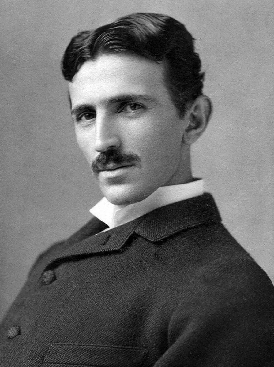
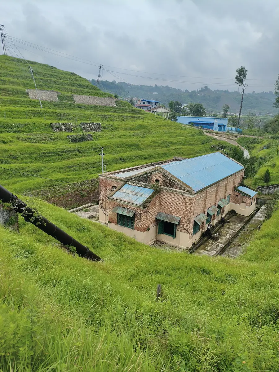
19.1 Introduction
Most of the electricity we use comes from generators: coils of wire turned in a magnetic field (or magnets turned inside coils) by water, steam or wind. As a coil turns steadily, the magnetic flux through it rises and falls, and the e.m.f. induced in it follows a sine curve. So a generator’s e.m.f., and the current it drives, vary sinusoidally with time:
- is the instantaneous e.m.f. or potential difference, its value at time ;
- is its greatest value, the peak value or voltage amplitude;
- is the angular frequency, in rad/s: , where is the frequency in hertz (Hz), the number of complete cycles in a second.
Whether you write sin or cos only decides where you start the clock: a cosine is a sine that started a quarter of a cycle earlier.
For example, if volts, then V and rad/s, so Hz.
Why does the world use a.c.? Mainly because a transformer can change an a.c. voltage up or down, and a transformer works only with a changing current. Power is sent across the country at very high voltage (132 kV and more on Nepal’s main lines), which means a small current, so little energy is lost as heat in the long wires (); near your home it is stepped down to a safe 230 V. With d.c. there was no simple way to do this until modern electronics.
A generator’s e.m.f. is volts. Its frequency is:
Pick an answer to see why.
19.2 Alternating current and e.m.f.
A current or e.m.f. whose size changes continuously with time and whose direction reverses periodically is called an alternating current or alternating e.m.f. (a.c.). Its instantaneous values are
where is the peak value of the current (the current amplitude) and the peak value of the e.m.f. (the voltage amplitude).
where is the period, the time for one complete cycle. In one cycle the current rises from zero to , falls through zero to (the minus sign means it flows the other way), and comes back to zero.
Nepal’s mains supply has a frequency of 50 Hz. How many times does the current change direction in one second?
Pick an answer to see why.
19.3 Root mean square (rms) value of a.c.
A meter on an a.c. supply shows one steady number, “230 V”, though the voltage is changing all the time. What does that number mean?
It is defined by heating, the thing every current does in a resistance:
The root mean square (rms) value of an alternating current is the steady (d.c.) current that, flowing through the same resistance for the same time, produces the same amount of heat as the alternating current does.
So the rms value is the a.c.’s d.c. equivalent for heating. It is written , or (the virtual value), or (the effective value). Every a.c. meter, and every label on an appliance, gives rms values unless it says otherwise.
Relation between the rms value and the peak value
Let the current through a resistance R be .
- Try the plain average first. Over a whole cycle, is positive for half the time and negative, by the same amounts, for the other half. So the average current is
(the angle brackets ⟨ ⟩ mean “the average over a cycle”). But the resistor certainly gets hot, so the plain average tells us nothing about the heating.
- The heating goes as I², which is never negative. The power is , whichever way the current flows. So average the square of the current:
- Match it with a steady current. A steady current gives power . For the same heating,
That is the name read backwards: the root of the mean of the square.
- Put in the sine:
- The mean of sin² over a cycle is ½. Since , and averages to zero over a cycle, . (Or: sin² and cos² have the same shape, one shifted from the other, so they have the same average; they add up to 1 at every instant, so each averages ½.)
- So
Mean value over half a cycle
Over a whole cycle the average current is zero, but over one half cycle (when the current flows one way) it is not. This mean value is what matters for charging a battery through a rectifier, or for electrolysis:
since and . So
For a sine wave, then, mean (half cycle) < rms < peak: . The rms value is larger than the mean because squaring gives the large values of the current more weight.
An a.c. ammeter in a circuit reads 2.0 A. The greatest current that actually flows is:
Pick an answer to see why.
19.4 Phasor diagram
Adding two alternating quantities, such as the voltages across a resistor and a coil in series, means adding two sine waves that rise and fall at different moments. Doing that with trigonometry at every instant is hard work. Engineers use a picture instead.
A phasor is an arrow that turns anticlockwise about the origin with the angular frequency of the a.c.:
- (a) The length of the phasor is the peak value of the quantity it stands for ( or ; or, scaled by , its rms value).
- (b) Its projection on the vertical axis at any instant is the quantity’s instantaneous value. An arrow of length at angle to the horizontal has vertical projection : exactly the a.c.
A phasor diagram shows the phasors of two or more alternating quantities of the same frequency, drawn at one instant. Since they all turn together at the same rate, the angles between them never change: the angle between two phasors is their phase difference . The one ahead in the direction of turning (anticlockwise) leads: it reaches its peak first. Phasors add like vectors, and the sum’s vertical projection is the sum of the instantaneous values.
You have met the idea before: in simple harmonic motion, the shadow of a point going round a circle moves as Grade 12: 2.2. A phasor is that turning radius.
On a phasor diagram the voltage phasor is drawn 90° anticlockwise from the current phasor. This means the voltage:
Pick an answer to see why.
19.5 A.c. through a resistor
Connect a resistor of resistance R (with no inductance) across an alternating e.m.f. . At every instant the p.d. across the resistor equals the e.m.f., and Ohm’s law holds at every instant, so the current is
Read the other way, if the current is (19.1), the p.d. is (19.2). Either way:
- the current and the e.m.f. are in phase (): they reach their peaks, pass through zero and reverse together;
- the peak (and rms) values obey Ohm’s law, , ;
- R does not depend on the frequency.
On a phasor diagram the two phasors lie along the same line, turning together.
19.6 A.c. through an inductor
Now connect a pure inductor, a coil of inductance L with no resistance, across the a.c. source. Let the current be
- The coil fights every change of current. A changing current in a coil induces a back e.m.f. in it (self-induction, Lenz’s law: Unit 18).
- Kirchhoff’s loop law. With no resistance in the circuit, the source’s e.m.f. and the back e.m.f. must add to zero ():
So the source’s voltage is largest when the current is changing fastest, not when it is largest.
- Differentiate the current:
- Name the quantity ωL. It has the dimensions of resistance (volts per ampere: in s⁻¹ × V s/A = V/A = Ω). It is the inductive reactance, the inductor’s opposition to a.c.:
- So . Writing and using :
Comparing (19.3) and (19.4): in a pure inductor the e.m.f. leads the current by 90° (π/2). Said the other way, the current lags the voltage by a quarter of a cycle. The voltage peaks when the current is passing through zero (changing fastest), and the current peaks a quarter of a cycle later, when the voltage has fallen to zero.
The peak values obey , and the rms values : “Ohm’s law” with the reactance in place of R, for peak or rms values (never for instantaneous ones, which are out of step).
Reactance and frequency
grows in proportion to the frequency. So:
- for d.c. (f = 0), : an ideal coil is just a piece of wire, a short circuit for d.c. (a real coil has only the small resistance of its wire);
- as the frequency rises, rises and the current falls: a coil lets low frequencies through and holds back high ones;
- at very high frequency, and the coil passes almost nothing.
That is why a coil is called a choke in a.c. work: it chokes a.c. while letting d.c. through.
Notice the shapes in Figure 19.9: the reactance is a straight line through the origin (it is proportional to f), and the current is a hyperbola (it is proportional to 1/f), very large at low frequency and falling towards zero at high frequency.
The frequency of the supply across a pure inductor is doubled, the voltage kept the same. The current:
Pick an answer to see why.
19.7 A.c. through a capacitor
Connect a capacitor of capacitance C across the a.c. source. A capacitor’s plates are separated by an insulator, so no charge ever crosses the gap. But as the voltage rises and falls, charge flows onto one plate and off the other, back and forth through the wires, and that back-and-forth flow is a real alternating current in the circuit.
Let the current in the wires be
- The capacitor’s p.d. With charge q on its plates, (19.6).
- Charge from current. The current is the rate at which charge arrives: , so .
- Integrate (taking q to swing evenly about zero, so no constant is left over):
- So the p.d. is
- Name 1/(ωC). It too has the dimensions of resistance. It is the capacitive reactance:
- The source’s e.m.f. equals the capacitor’s p.d. at every instant, . With and :
Comparing (19.5) and (19.7): in a capacitor the e.m.f. lags behind the current by 90°, or the current leads the voltage by a quarter of a cycle. It makes sense: the current is largest when the capacitor is empty and charge rushes on most easily; by the time the voltage has reached its peak, the capacitor is full and the current has stopped.
Again and .
Reactance and frequency
is inversely proportional to the frequency:
- for d.c. (f = 0), : a capacitor is an open circuit for d.c. Once it has charged, no steady current flows, since no charge crosses the insulator;
- as the frequency rises, falls and the current rises: a capacitor lets high frequencies through and blocks low ones, the opposite of a coil.
So a capacitor and a coil are opposites in every way. A coil passes d.c. and blocks high frequencies; a capacitor blocks d.c. and passes high frequencies. A loudspeaker box uses exactly this to send the bass to the big speaker (through a coil) and the treble to the small one (through a capacitor).
| Resistor | Pure inductor | Capacitor | |
|---|---|---|---|
| Opposition | resistance R | ||
| Change with frequency | none | ∝ f | ∝ 1/f |
| For d.c. (f = 0) | R | zero: a short circuit | infinite: an open circuit |
| Phase | V and I in phase | V leads I by 90° | I leads V by 90° |
| Peak current | |||
| Average power used | zero | zero |
Which of these lets a steady d.c. pass, but holds back a high-frequency a.c.?
Pick an answer to see why.
19.8 A.c. through an inductance and a resistance (LR circuit)
A real coil has both inductance and the resistance of its wire, so the LR circuit is the one you meet most often. Connect a resistance R and an inductance L in series across an a.c. source of e.m.f. V and frequency f, and let the current be .
In series, the same current flows through both, so draw the current’s phasor first, along the horizontal (OA). Then:
- the p.d. across R, , is in phase with the current: along OA;
- the p.d. across L, , leads the current by 90°: straight up (AB).
The supply’s e.m.f. is the sum of the two p.d.s at every instant, so its phasor is the vector sum OB. Since the two are at right angles, in the right-angled triangle OAB:
The total opposition of the circuit to a.c., , is its impedance Z:
measured in ohms. The phase angle by which the e.m.f. leads the current is the angle AOB:
So in an LR circuit the e.m.f. leads the current by an angle between 0 (all resistance) and 90° (all inductance).
19.9 A.c. through a capacitance and a resistance (CR circuit)
Now connect a capacitance C and a resistance R in series across the a.c. source, (19.12). Again the same current flows through both, so take the current along OA:
- is in phase with the current: along OA;
- lags the current by 90°: straight down (AB).
The e.m.f. is their vector sum OB, and in the right-angled triangle OAB:
where . The impedance of the CR circuit is
and the e.m.f. now lags behind the current by the angle , where
(In the sign convention of Section 19.10, where φ is the angle by which the e.m.f. leads, this φ is negative: .)
A resistor of 30 Ω and a capacitor of reactance 40 Ω are in series on a 100 V a.c. supply. The current is:
Pick an answer to see why.
19.10 A.c. through an inductance, a capacitance and a resistance (LCR circuit)
Now put all three in series: an inductance L, a capacitance C and a resistance R, across an a.c. source (19.16) of frequency f. The same current flows through all three; take it along OA. Then:
- is in phase with the current: along OA;
- leads the current by 90°: straight up;
- lags the current by 90°: straight down.
and point in exactly opposite directions, so they partly cancel. If , then , and their resultant is , upwards (AB). The supply’s e.m.f. is the vector sum OB:
The impedance of the LCR circuit is
and the angle by which the e.m.f. leads the current is given by
The LR and CR circuits are special cases: put (no capacitor; a capacitor shorted out) or (no coil).
The phase angle depends on which reactance is larger. There are three cases:
- (): is positive, so is positive: the e.m.f. leads the current. The circuit behaves like an LR circuit; we call it inductive.
- (): and are negative: the e.m.f. lags behind the current. The circuit behaves like a CR circuit: capacitive.
- (): the two reactances cancel completely, , so Z = R and . The circuit behaves as if it were a pure resistance: the current and e.m.f. are in phase, and the current is as large as it can be. This is resonance (Section 19.11).
In a series LCR circuit, , and . The circuit is:
Pick an answer to see why.
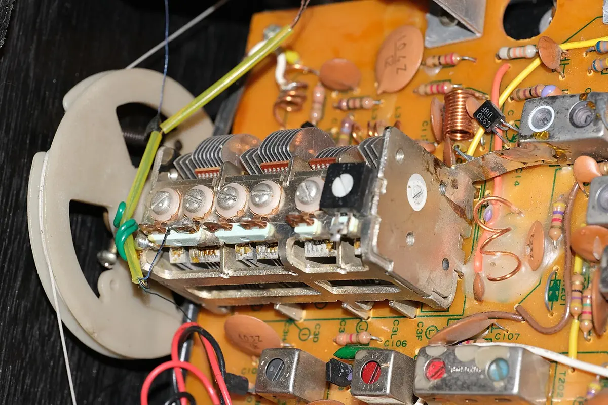
19.11 Resonance in a series LCR circuit
Push a child on a swing in time with its natural swing, and small pushes build up a large swing. When a body that can oscillate is driven by an outside force at its natural frequency, it oscillates with the greatest amplitude: resonance Grade 12: 2.7.
An LC circuit has a natural frequency too: a charged capacitor discharging through a coil makes the charge slosh back and forth between them, the energy swapping between the capacitor’s electric field and the coil’s magnetic field like a pendulum’s between potential and kinetic energy. When the frequency of the applied e.m.f. matches this natural frequency, the current becomes as large as it can be, and the current and the e.m.f. are in phase. This is electrical resonance.
The resonant frequency
The current is greatest when the impedance
is least. R doesn’t change with frequency, and the bracket, being squared, can never be negative: Z is least when the bracket is zero,
If is the frequency of the source at which this happens, , so
the resonant (natural) frequency of the series LCR circuit. At resonance:
- , and and are equal and opposite, so they cancel;
- Z = R, its least value, and the current is greatest: ;
- : the current and e.m.f. are in phase; the circuit acts as a pure resistance.
Notice that R plays no part in : it decides only how tall and how sharp the peak is.
The resonance curve
The current is , with . Leaving out the part that changes with time, , the amplitude of the current is
A graph of this current against the frequency f is the resonance curve. It is small at low frequency (where is huge), rises to a peak at , and falls again at high frequency (where is huge). The smaller the resistance, the taller and narrower the peak.
Figure 19.18 shows the same story the other way up: the impedance dips to R at the resonant frequency and rises on either side, so the current in Figure 19.17 peaks where Z dips.
In a series LCR circuit at resonance, which of these is not true?
Pick an answer to see why.
19.12 Quality factor of an LCR series circuit
At resonance something surprising happens. The current is large, , and with a small R it can be very large; so the p.d. across the coil, , and across the capacitor, , can be many times larger than the applied e.m.f. They cancel each other, so the supply never sees them, but a voltmeter across the capacitor alone would. A circuit with a small R on a 10 V supply can have hundreds of volts across its capacitor.
The quality factor (Q-factor) of a series LCR circuit measures this voltage magnification. It is the ratio of the p.d. across L (or across C) at resonance to the applied e.m.f.:
where is the current at resonance. At resonance , so
The quality factor also tells how sharp the resonance curve is: a high Q means a tall, narrow peak, which picks out one frequency and rejects its neighbors; a low Q, a low, broad one. One exact way to say it: the bandwidth , the width of the peak between the two frequencies where the power has fallen to half its peak value (the current to of its peak), is
So a radio’s tuning circuit wants a large Q (a small resistance) to separate stations close together.
Some important facts
- A coil with zero resistance uses no power (Section 19.13).
- A circuit containing a capacitor only uses no power.
- A series LCR circuit is used as a radio’s tuner.
- The quantities , and all have the dimensions of time (they are measured in seconds): is the time a coil’s current takes to build up, the time a capacitor takes to charge, and the period of an LC circuit’s natural oscillation.
- Self-induction is what makes a choke coil work (below).
- A.c. can be changed to d.c. by a rectifier, and d.c. to a.c. by an inverter (an oscillator with a switching circuit).
19.13 Power in an a.c. circuit
In an a.c. circuit both the e.m.f. and the current change all the time, so the power, the rate at which energy is delivered, changes too. The instantaneous power is the product of the instantaneous e.m.f. and the instantaneous current:
What matters for a bill or for heating is its average over a cycle.
The average power
Let the e.m.f. be and the current , lagging by φ (for a leading current φ is negative; the result is the same).
- Instantaneous power:
- Use the identity :
The first term is steady; the second swings at twice the supply frequency.
- Average over a cycle. The second term averages to zero, leaving
The peak power, when V and I are in phase, is , and the power then swings between 0 and , averaging . When they are out of phase, P is negative for part of each cycle: energy flows back from the circuit to the source, and the average is smaller.
- , what a voltmeter and an ammeter seem to promise, is the apparent power, in volt-amperes (VA);
- is the power factor;
- so average (real) power = apparent power × power factor, in watts.
Power factor
The power factor is the ratio of the real (useful) power to the apparent power:
It is the cosine of the phase angle between the voltage and the current. The phase angle φ lies between −90° (−π/2, all capacitance) and +90° (+π/2, all inductance), so cos φ is never negative: the power factor lies between 0 and 1. A power factor of 1 (100%) means every volt-ampere supplied does useful work; a low power factor means a large current flows back and forth for little real power.
Why does that matter, if the energy that flows back isn’t used? Because the current still flows in the wires. A factory whose motors (coils) give it a power factor of 0.5 draws twice the current it would at a power factor of 1 for the same real power, and the supply lines and transformers lose , four times as much heat. That is why electricity suppliers want large users to keep their power factor high, and factories put banks of capacitors beside their motors: the capacitors’ leading current cancels part of the motors’ lagging current, bringing φ closer to zero.
Special cases
- Pure resistance, : . The power factor is 1 and all the power supplied is used, as heat.
- Pure capacitance, : . The capacitor takes energy into its electric field for a quarter cycle and gives it all back in the next.
- Pure inductance, : . The coil stores energy in its magnetic field and returns it.
So the current through a pure inductor or a pure capacitor uses no power on average. Such a current is called a wattless current. That is the idea behind a choke coil: an inductor (with very little resistance) in series with a fluorescent tube or a fan’s speed regulator limits the current, as a resistor would, but wastes almost no energy as heat.
A coil draws 2 A from a 230 V a.c. supply, and a wattmeter shows it uses 92 W. Its power factor is:
Pick an answer to see why.
Exercise
Choose the correct option
- When 100 V d.c. is applied across a coil, a current of 1 A flows through it. When 100 V a.c. at 50 Hz is applied to the same coil, only 0.5 A flows. The inductance of the coil is:
Pick an answer to see why.
- In a series LCR circuit the resistance is 2 Ω, the capacitive reactance 4 Ω and the inductive reactance 4 Ω, on a 12 V supply. The current is:
Pick an answer to see why.
- In an inductor (a coil made to be an inductor), the reactance and the resistance R are related by:
Pick an answer to see why.
- The resonant frequency of a circuit is f. If the capacitance is made 4 times as large, the resonant frequency becomes:
Pick an answer to see why.
- The ratio of the mean value of a.c. over half a cycle to its rms value is:
Pick an answer to see why.
- In an LCR circuit the p.d. across the inductance is 60 V, across the capacitor 30 V and across the resistance 40 V. The supply voltage is:
Pick an answer to see why.
- A capacitor of capacitance 1 μF is charged to a potential of 1 V and then connected across an inductor of inductance 1 μH. The maximum current that flows in the circuit is:
Pick an answer to see why.
- A step-down transformer is connected to a 2400 V line, and a current of 80 A flows in its output load. The ratio of turns in the primary and secondary coils is 20 : 1. If the transformer is 100% efficient, the current in the primary coil is:
Pick an answer to see why.
- The reactance of a capacitor of C μF for a.c. of frequency Hz is 25 Ω. The value of C is:
Pick an answer to see why.
- What is the phase difference between the rms (virtual) voltage and current when the current in a circuit is wattless?
Pick an answer to see why.
Answer these questions
An alternating current I varies with time t as shown in the graph above. Use the graph to answer:
- a.What is the peak value of the current?
- b.What is the current at t = 0.23 s?
- c.Find the period and frequency of the current.
- d.Find the rms value and the mean value (over half a cycle) of the current.
Hint
Answer
- a.What is the power factor of a purely capacitive circuit?
- b.Obtain an expression for the phase relationship between the current and the voltage in a purely capacitive circuit.
- c.Why is a purely capacitive circuit an open circuit for d.c.?
- d.An iron-cored coil of 2 H and 50 Ω resistance is placed in series with a resistor of 450 Ω, and a 200 V, 50 Hz a.c. supply is connected across them. Find the current in the coil, its phase angle relative to the supply voltage, and the p.d. across the coil.
Hint
Answer
a. Define the rms value of a.c.
The graph above shows how the sinusoidal current I in a resistor of 450 Ω varies with time t. Use it to find, for the time from t = 0 to t = 30 ms:
- b.the frequency of the current;
- c.the mean current;
- d.the rms current;
- e.the energy dissipated in the resistor.
Hint
Answer
- a.What is the power factor of a purely inductive circuit?
- b.Obtain an expression for the phase relationship between the current and the voltage in a purely inductive circuit.
- c.Why is a purely inductive circuit a short circuit for d.c.?
- d.A coil with inductance and resistance is connected to an oscillator giving a fixed sinusoidal output of 5 V rms. At 50 Hz the rms current in the coil is 1 A, and at 100 Hz it is 0.625 A. Find the inductance of the coil.
Hint
Answer
An inductor, a capacitor and a resistor are connected in series with a source of alternating voltage, as above.
- a.Write the relationship between the current and the voltage.
- b.Draw a phasor diagram to show the leading or lagging relation between the voltage and the current.
- c.In the series LCR circuit, R = 25 Ω, L = 30 mH and C = 10 μF, connected to a 240 V, 50 Hz a.c. source. Calculate the current and the voltmeter reading across the capacitor.
Hint
Answer
- a.Write the expression for the impedance of an LCR circuit.
- b.Find the condition for resonance in an LCR circuit.
- c.A circuit consists of a capacitor of 2 μF and a resistor of 1000 Ω. An alternating e.m.f. of 12 V (rms), 50 Hz is applied. Find the current, the p.d. across the capacitor and the phase angle between the applied e.m.f. and the current.
Answer
The graph shows how the e.m.f. and the current vary with time in an LCR series circuit.
- i.Is the phase constant φ (the angle by which the e.m.f. leads the current) positive or negative? Explain.
- ii.Sketch a phasor diagram for this case.
- iii.Is the circuit more inductive or more capacitive? Explain.
- iv.To increase the rate at which energy is delivered to the resistance, should the inductance be increased or decreased? Justify your answer.
Hint
Answer
- a.The graph in question 13 shows how the sinusoidal current in a 450 Ω resistor varies with time. Use it to find, for t = 0 to t = 30 ms: i. the frequency of the current; ii. the energy dissipated in the resistor.
- b.Discuss the phase relationship between the voltage and the current in an a.c. circuit with a capacitor and a resistor in series, and so derive the expression for the impedance of the circuit.
- c.An air-cored coil and an electric bulb are connected in series across a 220 V, 50 Hz a.c. supply, and the bulb glows with some brightness. How will its glow change if a capacitor is added in series?
Answer
- a.Define the impedance of an LCR circuit.
- b.The series LCR circuit above is connected across an a.c. source of e.m.f. 50 V and 50 Hz. i. Calculate the impedance of the circuit, if L = 60 mH, C = 0.50 μF and R = 300 Ω. ii. How does resonance occur in this circuit? Write the expression needed.
- c.A device X is connected across an a.c. source of voltage , and the current through X is . i. Identify the device X, and write an expression for its reactance. ii. Draw a graph of the voltage and the current over one cycle for X.
Answer
- a.What is wattless current?
- b.Figures a, b and c above show three a.c. circuits with equal currents. i. If the frequency of the e.m.f. is increased, what happens to the current in each? Explain. ii. What difference do you expect in the opposition to the current in circuits a and b if the a.c. e.m.f. is replaced by an equivalent d.c. e.m.f.?
Answer
- a.Define resonance in an a.c. circuit, with one example.
- b.Prove that the resonant frequency of an a.c. series LCR circuit is .
- c.The maximum capacitance of a variable capacitor is 33 pF. What self-inductance must be connected to it for the natural frequency of the LC circuit to be 810 kHz, a frequency in Radio Nepal’s medium-wave (AM) band?
Answer
Printable PDFs
- The unit as a book (A5) 38 pages Answers as an A4 booklet, 10 sheets
- Study notes 3 pages
- Worksheet 4 pages Answer key
- Harder practice questions 2 pages Answer key
Quiz yourself: Electricity and Magnetism, Grades 5–12 →
Practice every question in the book, and keep track of the ones you miss →
A companion to your textbook, not a replacement for it: study from the book your school uses, and where the two differ, follow your teacher. Found a mistake? Please tell us.