
Press the shutter of a camera in a dark room, and the flash fires: a burst of light thousands of times more powerful than the camera’s small battery could ever drive directly. Under the cover of every ceiling fan in Nepal sits a small cylinder that gives the motor its first push. Inside your phone, a few thousand tiny parts keep its voltage steady while the processor gulps current in bursts, and its touch screen knows where your finger is because your finger changes how much charge the screen can hold.
All of these are capacitors: two conductors kept close together but apart, which store electric charge, and with it energy, for a moment. In this unit you will see how a capacitor stores charge, what its capacitance is and how to calculate it for a pair of plates, why an insulator between the plates helps, how capacitors combine, and how much energy a charged capacitor holds.
22.1 Introduction
A capacitor is a component of an electric circuit that stores electric charge for a while. Inside, it separates charge: one side becomes positive, the other equally negative.
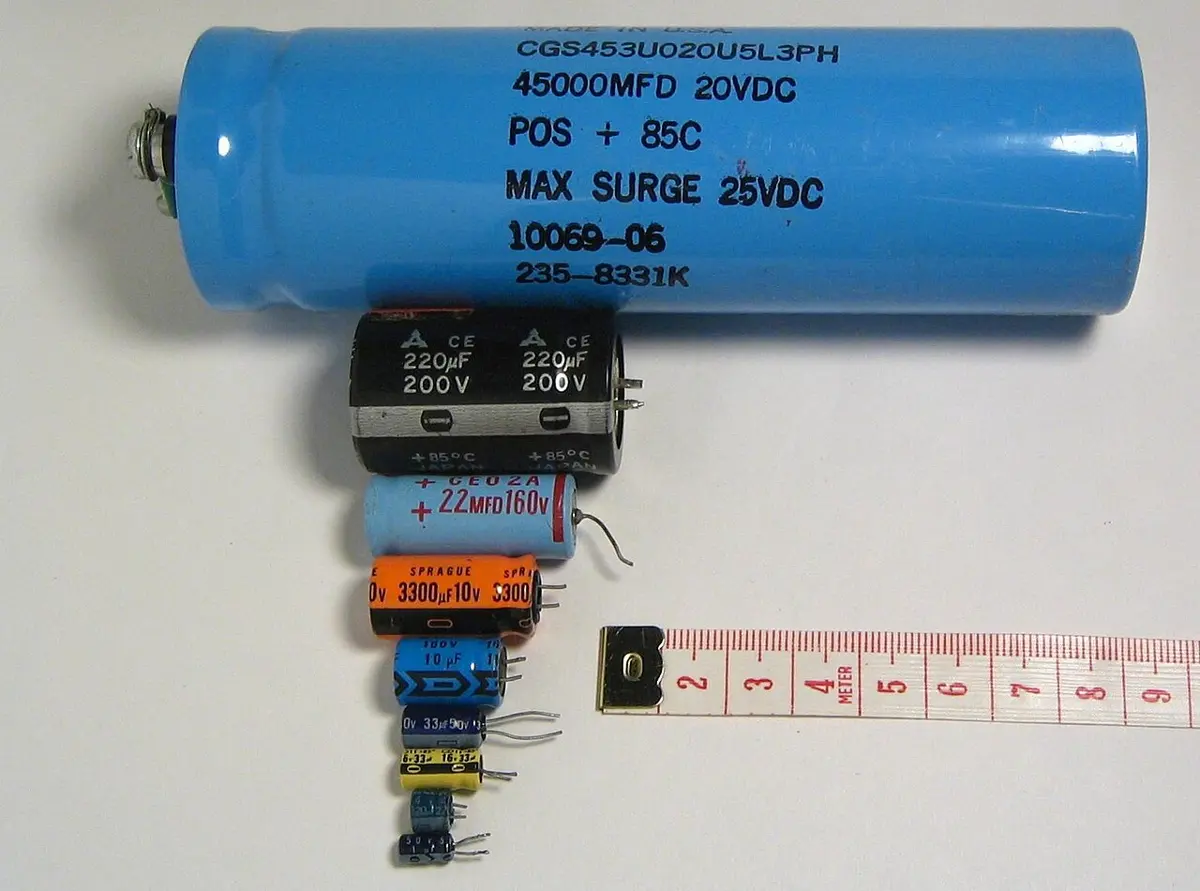
Capacitors come in many shapes and sizes, from specks smaller than a grain of rice to cans as big as a water bottle, but every one is built the same way: two metal plates separated by an insulator. The insulator is called the dielectric: air, paper, plastic film, ceramic, mica or a thin layer of metal oxide.
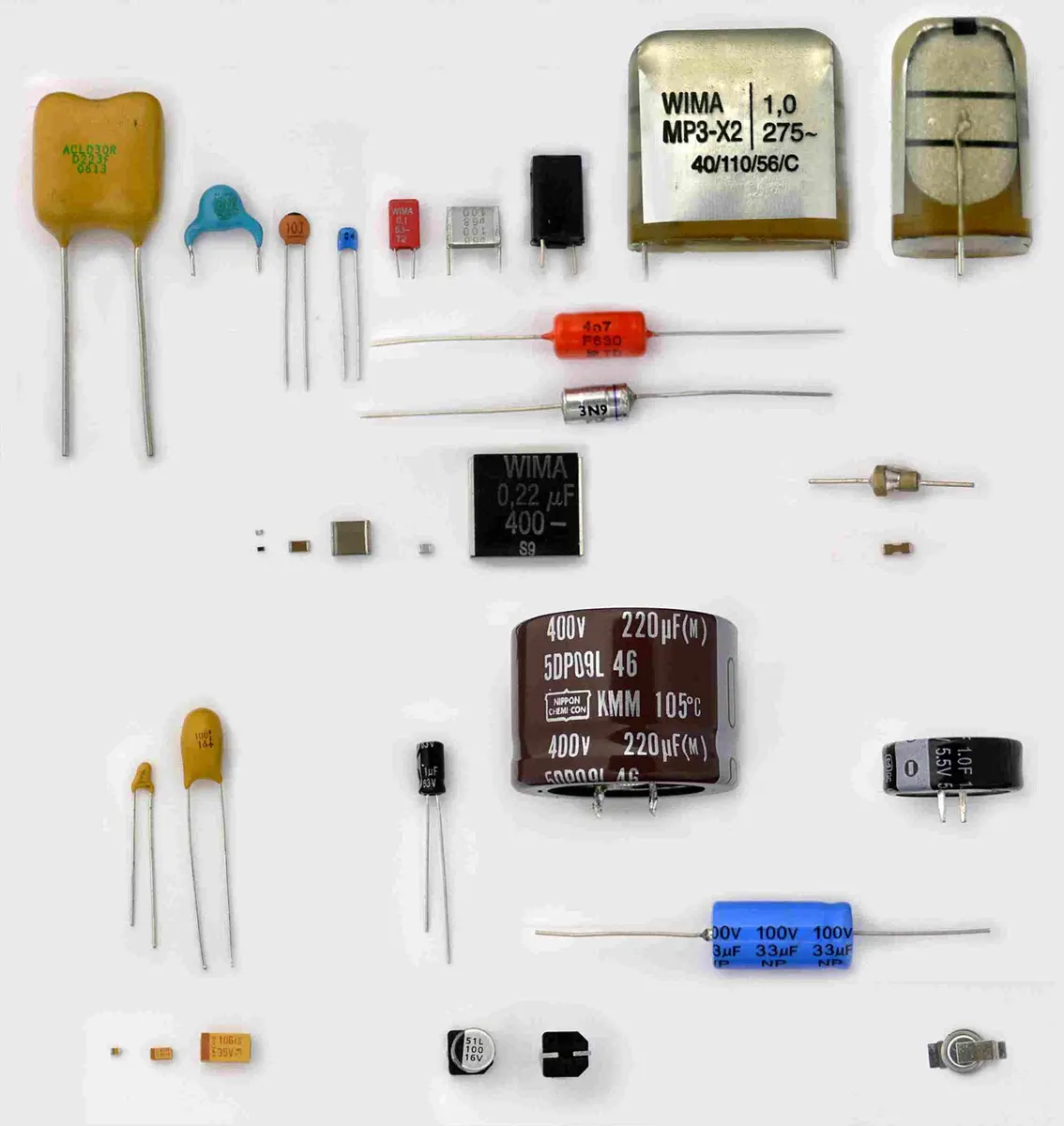
The circuit symbol shows the two plates edge-on, two short parallel lines with a gap between them, with a wire joined to the middle of each.
You can make a capacitor at home from two sheets of aluminium foil with a sheet of newspaper between them.
The two plates of a capacitor are separated by:
Pick an answer to see why.
22.2 Storing charge
Connect a capacitor to a cell (Figure 22.3). For a very short time, a current flows:
- The cell’s positive terminal pulls electrons off plate A, and its negative terminal pushes the same number of electrons onto plate B. No electron crosses the gap: the insulator stops them.
- Plate A, having lost electrons, has a net positive charge, +Q. Plate B, having gained them, has a net negative charge, −Q.
- Why equal? The current is the same at every point of the series loop, and charge is conserved: every electron that leaves A arrives, by way of the cell, on B. So the two plates always carry equal and opposite charges.
- The separated charges make a potential difference across the plates, which pushes back against the cell. As more charge piles up, this p.d. grows, and the current gets smaller.
- When the p.d. across the plates equals the cell’s e.m.f. E, nothing pushes the electrons any more: the current stops, and the capacitor is fully charged.
The total charge on the capacitor is still zero: +Q + (−Q) = 0. A capacitor doesn’t store charge the way a tank stores water; it separates charge into +Q on one plate and −Q on the other. When we say “a capacitor stores a charge Q”, we mean the size of the charge on either plate.
Take the charged capacitor out of the circuit, and the charges stay where they are, held by their attraction across the gap. Join its plates through a lamp, and the extra electrons on B flow round to A: the lamp glows for a moment while the capacitor discharges.
A capacitor is fully charged from a 9 V battery, with +20 µC on one plate. The total charge on the capacitor is:
Pick an answer to see why.
22.3 Capacitance
Join a capacitor to a battery with wires (Figure 22.4). The plates quickly charge, one positive and one equally negative. Each terminal of the battery and the plate joined to it are at the same potential (a wire with no current through it has no p.d. across it), so once the current has stopped, the full battery voltage is across the capacitor.
Now repeat with batteries of different voltages. For a given capacitor, the charge Q on each plate is found to be directly proportional to the p.d. V between the plates: twice the voltage, twice the charge.
The ratio Q/V is therefore fixed for each capacitor. It is the capacitor’s capacitance, C:
The capacitance of a capacitor is the charge stored (on either plate) per unit potential difference across it. It measures how much charge the capacitor stores for each volt, and so, in everyday words, its ability to store charge. A capacitor with a large capacitance stores a lot of charge at a low voltage.
Notice what it does not depend on: Q and V change together, but their ratio stays the same. Capacitance depends only on how the capacitor is built (Section 22.4). Commercial capacitors have it printed on them, “470 µF”, beside the highest voltage they can safely take.
The farad
The SI unit of capacitance is the coulomb per volt, called the farad (F), after Michael Faraday:
A capacitor has a capacitance of one farad if a charge of one coulomb on its plates gives a p.d. of one volt between them.
In base units: , with 1 C = 1 A s and 1 V = 1 J/C = 1 kg m² s⁻³ A⁻¹, so
A coulomb is a lot of charge, so a farad is a huge capacitance. Most capacitors are measured in smaller units:
| Unit | Symbol | Value | A typical use |
|---|---|---|---|
| millifarad | mF | 10⁻³ F | a large smoothing capacitor in a power supply |
| microfarad | µF | 10⁻⁶ F | a ceiling fan’s capacitor (2–4 µF), a camera flash (a few hundred µF) |
| nanofarad | nF | 10⁻⁹ F | the foil-and-newspaper capacitor above |
| picofarad | pF | 10⁻¹² F | the capacitors that tune a radio |
A capacitor holds 60 µC at 12 V. If the p.d. across it is raised to 18 V, its capacitance:
Pick an answer to see why.
22.4 Parallel-plate capacitor
The simplest capacitor is two flat, parallel metal plates separated by an insulator: a parallel-plate capacitor. The insulator can be a vacuum, air or another gas, or a solid such as plastic.
Its capacitance depends on three things:
- the area A of the plates (more room for charge to spread out);
- their distance apart d (closer plates hold charge more strongly);
- the insulator between them, through a property called its permittivity, ε.
Permittivity
Put an insulator in an electric field and its molecules are pulled slightly out of shape or turned: it is polarized (Section 22.5). The polarized insulator sets up a field of its own that partly cancels the applied field. Permittivity measures how strongly a material does this: the higher its permittivity, the more it weakens the field due to a given charge, so the more charge the plates can hold at a given p.d.
Permittivities are given relative to the permittivity of free space (a vacuum), :
The relative permittivity of a material, also called its dielectric constant K, is how many times greater its permittivity is than that of a vacuum. Its absolute permittivity is then
| Material | Relative permittivity |
|---|---|
| vacuum | 1 (exactly) |
| air | 1.0006 (taken as 1) |
| Teflon (PTFE) | 2.1 |
| polystyrene | about 2.6 |
| paper | about 2–4 |
| mica | about 5–7 |
| glass | about 5–10 |
| pure water | about 80 |
| barium titanate (a ceramic) | 1000 and more |
Dielectrics used in capacitors include paper, mica (a mineral that splits into thin sheets), Teflon and other plastics, ceramics, and the oxides of metals such as aluminium and tantalum.
Deriving the capacitance
The charges +Q and −Q spread evenly over the inner faces of the plates. Between the plates, apart from near the edges, the field is uniform: straight, parallel field lines from the + plate to the − plate.
The field between the plates. By Gauss’s law (Unit 20), the field between two large, oppositely charged parallel plates, each with a charge σ per unit area, is . Here , so
The p.d. across a uniform field. In a uniform field, the p.d. between two points a distance d apart along the field is (Unit 21), so
The capacitance. By definition,
and Q cancels:
With a dielectric filling the gap, replace by the material’s permittivity :
So C depends only on the geometry (A and d) and the material (), never on Q or V. A dielectric multiplies the capacitance by ; with air the change is negligible.
This also gives the unit of : has the unit F m/m² = F/m, the farad per meter.
Change the plates and the insulator below and watch the capacitance.
The plates of a parallel-plate capacitor are moved twice as far apart, and their area is doubled. Its capacitance:
Pick an answer to see why.
A capacitor with air between its plates has a capacitance of 50 pF. The gap is filled with mica of relative permittivity 6. Its capacitance becomes:
Pick an answer to see why.
22.5 Dielectric strength of dielectrics
Raise the p.d. across a capacitor and the field between its plates, , grows. At some field the insulator can’t hold out: electrons are torn loose from its atoms, the dielectric suddenly conducts, and a spark jumps between the plates. Usually that ruins a solid dielectric for good.
The dielectric strength of an insulator is the greatest electric field it can withstand without breaking down.
| Dielectric | Dielectric strength |
|---|---|
| dry air at sea level | about 3 kV/mm (3 × 10⁶ V/m) |
| paper | about 15 kV/mm |
| Teflon | about 60 kV/mm |
| mica | about 100 kV/mm and more |
For air the exact value depends on the temperature, the pressure and how dry the air is. Lightning is air breaking down on a huge scale: the strong fields between charged clouds, or between a cloud and the ground, tear electrons off air molecules and open a conducting path. (A lightning stroke starts at fields lower than 3 kV/mm, because the field is far stronger close to raindrops and ice crystals, and the breakdown grows from there.)
So every capacitor has a voltage rating, printed beside its capacitance (“470 µF 25 V”): the highest p.d. it can safely take. A thin dielectric gives a large capacitance but breaks down at a lower voltage.
What a dielectric does
An insulator between the plates does two jobs for a capacitor’s designer:
- it keeps the plates apart at a fixed, small distance, which a gap of air can’t do for flexible foils;
- it increases the capacitance, by its relative permittivity.
Every material has a permittivity greater than a vacuum’s. To include it, replace by wherever it appears.
Why a dielectric increases the capacitance
A dielectric is an insulator that is polarized in an electric field. In many dielectrics each molecule is already slightly positive at one end and negative at the other (a polar molecule, like water); in others the field itself pulls each molecule’s electrons slightly one way and its nuclei the other. Either way, in the capacitor’s field the molecules line up, or are stretched, with their positive ends pointing along the field.
Look at the dielectric’s faces (Figure 22.7). Inside it, the + and − ends of neighboring molecules cancel. But the face next to the positive plate is left with a layer of negative ends, and the face next to the negative plate with positive ends. These surface charges make a field of their own, , pointing against the capacitor’s field:
Now follow it through for a capacitor charged and then disconnected, so that Q can’t change:
- The net field between the plates is smaller (it is ).
- The p.d. across the plates, , is smaller, since d is fixed.
- The charge Q is unchanged, so the capacitance is larger, by the factor .
Another way to say it: the dielectric’s negative face partly cancels the positive plate’s charge, lowering its potential, and its positive face raises the potential of the negative plate. The p.d. between the plates falls.
If the capacitor stays connected to a battery instead, the p.d. stays at the battery’s voltage, and the battery pushes more charge onto the plates until the net field is back to V/d: again Q/V goes up by .
What happens to the stored energy of the disconnected capacitor? It falls, because the p.d. falls while Q stays the same (Section 22.7). The field pulls the dielectric into the gap, doing work on it: a slab held at the edge of a charged capacitor is sucked in. This simple picture of surface charges explains most of what a dielectric does; a full treatment also counts how the field inside the material varies from molecule to molecule.
A capacitor is charged and disconnected from the battery. A slab of glass is then slid in to fill the gap. Which of these goes up?
Pick an answer to see why.
Practical capacitors
To get a large capacitance into a small space, designers make the plate area A large and the gap d tiny, and choose a dielectric with a high permittivity.
- Ceramic capacitors: small discs or chips with a ceramic dielectric of high ; picofarads to microfarads.
- Film capacitors: metal foil or metallized plastic film, rolled up with a plastic film between; nanofarads to microfarads. A ceiling fan’s capacitor is one.
- Electrolytic capacitors: the largest capacitance for their size, microfarads to farads.
In an aluminium electrolytic capacitor (Figure 22.8), the layers are rolled up together, rather like rolling up three carpets laid one on another. The dielectric is a layer of aluminium oxide grown on the positive foil, so thin (well under a micrometer) that d is tiny, and the foil is etched rough so that its area is many times its flat size: both make C large. The conducting electrolyte in the paper fills every pit of the rough surface and carries the charge to the other foil.
An electrolytic capacitor must be connected the right way round: its oxide layer is kept in place only while the + foil is at the higher potential. Connected backwards, the oxide is broken down, a current flows, the electrolyte boils, and the can may burst. That is why such capacitors have a stripe marking the − lead, and a + on the circuit symbol.
22.6 Combination of capacitors
Capacitors are made in a set of standard values (1.0, 2.2, 4.7, 10 µF…). To get a value that isn’t made, or a larger capacitance, or one that can take a higher voltage, we connect capacitors together. Like resistors, they can be joined in parallel, in series, or in a mixture of both.
22.6.1 Capacitors in parallel
In parallel, each capacitor is connected directly across the same two points (Figure 22.10). For two or more capacitors in parallel:
The p.d. is the same across each capacitor, the supply’s p.d. V (each plate is joined by wire to one terminal).
The charges add. Charge is conserved, so the total charge the supply delivers is shared among the capacitors:
Each charge is , .
One equivalent capacitor C, with the same V, would hold the same total Q: . So
Dividing by V:
The total capacitance of capacitors in parallel is the sum of their capacitances, larger than any one of them. It is as if their plate areas were added: the combination stores more charge at the same p.d.
22.6.2 Capacitors in series
In series, the capacitors are joined one after the other in a single line (Figure 22.11).
Why do they all store the same charge, even when their capacitances differ? The supply is connected only to the outer plates: the left plate of C₁ and the right plate of C₂. These take +Q and −Q as electrons flow off one and onto the other. The two inner plates are joined to each other by a wire, but cut off from the supply by the dielectrics on either side. The +Q on C₁’s left plate attracts electrons to C₁’s right plate, which becomes −Q; those electrons come from C₂’s left plate, which is left with +Q. The two inner plates together stay neutral. So each capacitor has +Q on one plate and −Q on the other: the same charge Q, whatever its capacitance. (Each capacitor’s total charge is zero, as always.)
For two or more capacitors in series:
The charge is the same on each capacitor: .
The p.d.s add to the supply’s p.d. (energy is conserved: each coulomb gives up its energy in the capacitors one after the other):
Each p.d. is , .
One equivalent capacitor C would hold the same Q at the same total V: . So
Dividing by Q:
For two capacitors this gives a handy form: (product over sum).
The total capacitance of capacitors in series is less than the smallest of them: the combination stores less charge at a given p.d. It is as if their gaps were added. But the supply’s p.d. is shared among them, so a series string can take a higher voltage than one capacitor alone.
Three capacitors of 6 µF each are joined in series. Their combined capacitance is:
Pick an answer to see why.
A 2 µF and a 4 µF capacitor are in series across 12 V. The p.d. across the 2 µF capacitor is:
Pick an answer to see why.
Mixed capacitor combinations
To find the capacitance of a network, and the charge and p.d. of each capacitor in it:
- Combine capacitors that are clearly in series or in parallel, using the formulas above.
- Redraw the circuit after every combination.
- Repeat steps 1 and 2 until only a single equivalent capacitor is left.
- Find the charge on that single capacitor, using .
- Work backwards through the diagrams to the original one, finding the charge and p.d. of each capacitor on the way, using these facts:
- A. the capacitor equation: ;
- B. capacitors in parallel: ;
- C. capacitors in parallel all have the same p.d. V, as does their equivalent capacitor;
- D. capacitors in series: ;
- E. capacitors in series all have the same charge Q, as does their equivalent capacitor.
22.7 Energy stored in a capacitor
Charge a 1000 µF capacitor from a 9 V battery, take it out of the circuit, and touch its leads to a small LED (with a 100 Ω resistor in series). The LED flashes brightly for a moment, with no battery in sight. The flash is the evidence: a charged capacitor stores energy. A camera’s flash and the defibrillator that restarts a heart both work this way, storing energy slowly and giving it out all at once.
How much energy is stored depends on the capacitance and on the p.d. the capacitor was charged to. (A tiny 1000 pF capacitor charged to 3 V holds only about 4.5 billionths of a joule: far too little to light anything you could see.)
Where the energy comes from
An electron arriving at the negative plate is repelled by all the electrons already on it, so work must be done to push it on. An electron leaving the positive plate is attracted back by the positive charge there, so work must be done to pull it off (Figure 22.13). The battery or power supply does this work. The more charge already on the plates, the harder each new bit is to move.
The work is not lost: it is stored as electric potential energy of the separated charges, in the field between the plates. It comes from the energy of the battery, and it comes back out when the capacitor discharges.
Deriving the energy stored
By definition of p.d., moving a charge Q through a p.d. V takes work W = QV. But while a capacitor charges, its p.d. doesn’t stay the same: it grows in step with the charge, Q = CV.
A small step. At a moment when the p.d. is V, adding a small charge ΔQ (so small that V hardly changes) takes work
On the graph of V against Q (Figure 22.14), this is the area of the thin strip of height V and width ΔQ.
All the steps. Adding all the strips from zero to the final charge Q gives the area under the graph. So the area under a p.d.–charge graph equals the work done, which is the energy stored.
The triangle. The graph is a straight line from the origin to (Q, V), so the area is a triangle:
where V is the p.d. when the charge is Q.
In terms of C and V. Put Q = CV:
In terms of Q and C. Put :
So there are three equations for the energy stored, all the same thing:
By calculus: the work to add dQ at p.d. is , and .
Why the half? Each bit of charge is carried across the p.d. of its moment, which rises from 0 to V: on average across V/2.
For a given capacitor, W ∝ V²: doubling the p.d. quadruples the energy stored.
The p.d. across a capacitor is increased from 3 V to 9 V. The energy it stores becomes:
Pick an answer to see why.
Exercise
Choose the correct option
- What is the charge stored on a 220 µF capacitor with a 6 V p.d. across it?
Pick an answer to see why.
- Two capacitors, P and Q, are both charged by the same 12 V battery. The capacitance of P is 4200 µF and that of Q is 420 µF. Which gives the correct ratios of the energy and the charge stored by each capacitor?
Pick an answer to see why.
- The graph above shows how the p.d. across a capacitor varies with the charge stored on it. Which gives the correct capacitance and the energy stored when the p.d. across it is 12 V?
Pick an answer to see why.
Answer these questions
The p.d. of a test circuit was measured as a capacitor was charged, and the graph below was plotted from the data.
- a.Explain what is meant by the term “capacitance”.
- b.Calculate the capacitance of the capacitor.
Hint
Answer
In the figure below, a p.d. of 12 V is applied between P and Q.
- a.Calculate the charge on each capacitor.
- b.What single capacitor placed between P and Q would be equivalent to the two shown? Comment on your answer.
Answer
In the figure below, a p.d. of 12 V is applied between P and Q.
- a.What is the p.d. across each capacitor? Explain your answer.
- b.What single capacitor placed between P and Q would be equivalent to the two shown? Comment on your answer.
Answer
The figure below shows how the p.d. across a capacitor changes as it is charged.
- a.What is the capacitance of the capacitor?
- b.Calculate the energy stored in the capacitor when it has a charge of 100 µC, 200 µC and 500 µC.
- c.Sketch a graph of the energy stored against the charge.
Hint
Answer
A capacitor with a capacitance of 137 pF is charged until it stores a charge of 2.47 nC, and is then disconnected. It has a dielectric with a relative permittivity of 3.1. The dielectric is removed, so there is now a vacuum between the plates, but nothing else is changed. Calculate the change in the p.d. across the capacitor.
Hint
Answer
An 8.0 µF capacitor is fully charged from a 12 V supply. Calculate the energy stored by the capacitor.
Answer
Printable PDFs
- The unit as a book (A5) 18 pages Answers as an A4 booklet, 5 sheets
- Study notes 3 pages
- Worksheet 5 pages Answer key
- Harder practice questions 2 pages Answer key
Quiz yourself: Electricity and Magnetism, Grades 5–12 →
Practice every question in the book, and keep track of the ones you miss →
A companion to your textbook, not a replacement for it: study from the book your school uses, and where the two differ, follow your teacher. Found a mistake? Please tell us.