
The lights go out. Load shedding again. Within a minute someone switches on a rechargeable emergency lamp, the inverter in the corner starts to beep, a neighbor pulls the cord of a small petrol generator, and on the roof a solar panel keeps quietly charging a battery. Four ways of getting electricity, and they are not all the same kind of electricity.
This unit is about the two kinds of current, direct and alternating, and about the deep link between electricity and magnetism. A current makes a magnet; a magnet that moves makes a current. Those two facts run nearly everything that plugs into a wall: the fan above you, the motor in a water pump, the generators deep inside Nepal’s hydropower stations, and the little transformer that charges your phone.
Direct current and alternating current
Direct current (d.c.)
Connect a dry cell to a bulb with a switch and turn it on. The bulb glows, steadily, for as long as the cell lasts. Inside the wire, the electric charges move in one direction only, round and round the circuit. A cell has a fixed positive terminal (+) and a fixed negative terminal (−), and they never swap.
A solar panel lighting a bulb does the same: its charges also flow in one fixed direction. A current that flows in one direction only is called direct current (d.c.). Dry cells, solar panels (photocells) and batteries are sources of d.c.
Alternating current (a.c.)
A dynamo on a bicycle also lights a bulb, but look closely at it and you won’t find a + and a − terminal. Inside it, a magnet spins next to a coil of wire. As the magnet turns, the charges in the wire are pushed forward, then backward, then forward again. The current keeps changing direction. Its size changes too: it grows from zero to the largest value, falls back to zero, grows the other way, and falls to zero again, over and over.
A current whose size and direction change again and again, at regular intervals, is called alternating current (a.c.). Dynamos and a.c. generators are sources of a.c. The electricity in the sockets of your home is a.c., made by huge generators in power stations.
Which of these is a source of alternating current?
Pick an answer to see why.
The current–time graph
A graph of current against time shows the difference at once.
- In the d.c. graph, the current is a flat line: the same 4 A at every moment.
- In the a.c. graph, the current rises from 0 to 5 A, falls to 0, then rises again in the opposite direction to −5 A, and falls back to 0. One complete wave like this is a cycle.
The number of cycles completed in one second is the frequency of the a.c. Its unit is the hertz (Hz): one cycle per second is 1 Hz.
The a.c. supply in Nepal has a frequency of 50 Hz, and a voltage of about 230 V (anything between about 220 V and 240 V is normal). 50 Hz means 50 cycles every second. In each cycle the current flows one way and then the other, so it changes direction 100 times every second. The time for one cycle is 1/50 s = 0.02 s, exactly as in Figure 11.3.
D.c. never changes direction, so its frequency is zero.
Which devices use which?
Some things run on a.c., some on d.c., and some on both.
| Runs on a.c. | Runs on d.c. (inside) | Runs on either |
|---|---|---|
| ceiling fans, water pumps, refrigerators (their motors) | mobile phones, computers, TVs, LED lights (their circuits) | electric heaters, irons, filament bulbs |
Heaters and filament bulbs only need the current to heat a wire, and a wire heats up whichever way the current flows. Electronic circuits need d.c. So how does a laptop run from an a.c. socket? Its adapter contains a rectifier, a device that turns a.c. into d.c.
Activity 11.1: d.c. and a.c. compared
The magnetic effect of electric current
In 1820, the Danish physicist and teacher Hans Christian Oersted was giving a lecture with an electric circuit on his table. A magnetic compass happened to be lying near a wire. When the current flowed, the compass needle swung. When he reversed the current, the needle swung the other way. A compass needle only turns when there is a magnetic field, so the current itself must be making one.
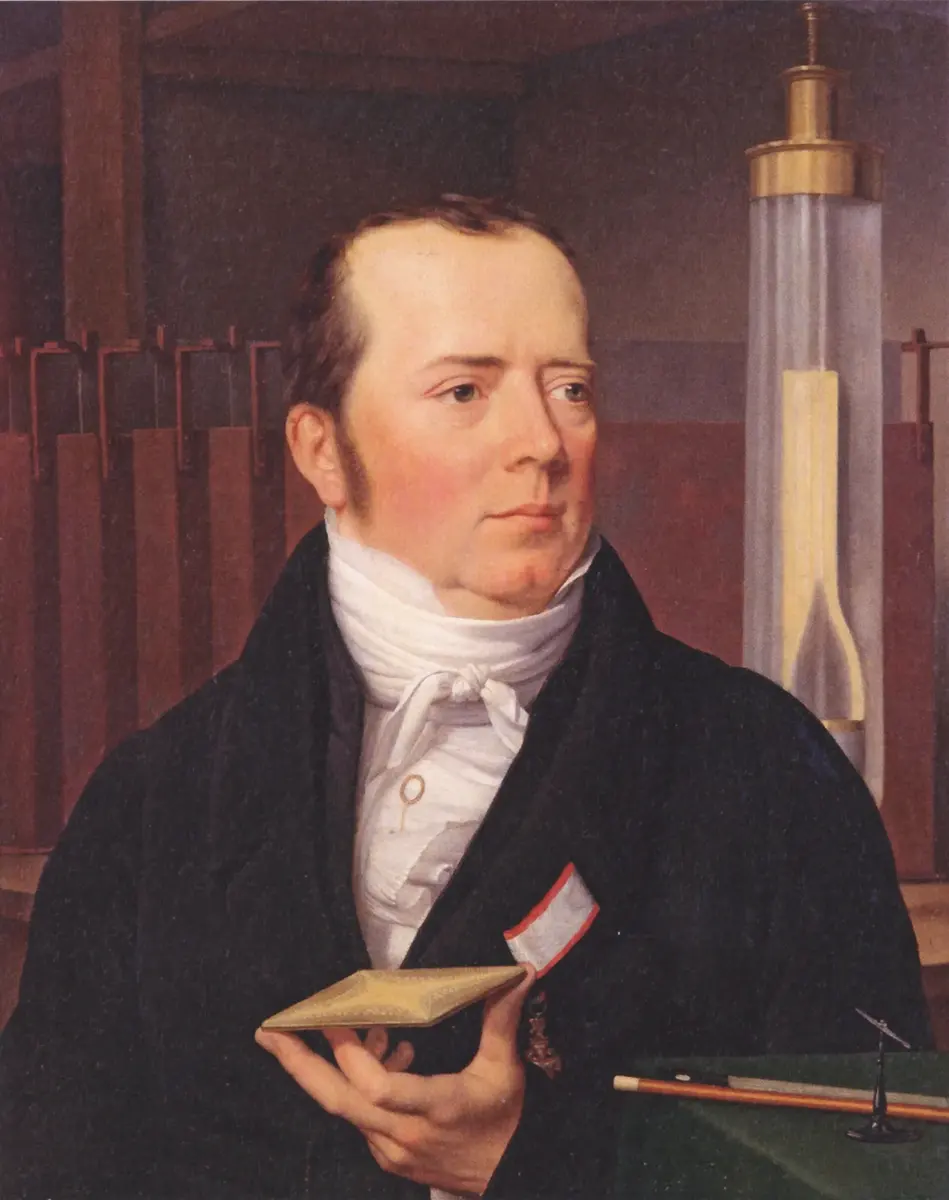
The formation of a magnetic field around a conductor when a current flows in it is called the magnetic effect of current. The direction of this field depends on the direction of the current.
A compass is placed under a wire. When a current flows, the needle turns towards the east. What happens if the current is reversed?
Pick an answer to see why.
The magnetic field around a straight wire
The field lines around a straight wire are concentric circles, centered on the wire. The field is strongest close to the wire and gets weaker further away. Seen from above, if the current flows upwards (towards you, out of the card), the field goes anticlockwise. If the current flows downwards (into the card), the field goes clockwise.
Maxwell’s right-hand thumb rule
You don’t need compasses to find the direction of the field. Use your right hand.
Maxwell’s right-hand thumb rule: Imagine gripping the wire with your right hand, with your thumb pointing in the direction of the current. Your curled fingers then point in the direction of the magnetic field lines around the wire.
A long straight wire hangs vertically, and the current flows downwards. Seen from above, the field lines around it go:
Pick an answer to see why.
The magnetic field around a solenoid
A solenoid is a long, cylindrical coil of insulated wire. It is made by winding insulated wire round and round a tube. When its ends are connected to a cell, a current flows round every loop, and a magnetic field forms in and around it.
- Outside, the field of a solenoid looks just like the field of a bar magnet: the lines come out of one end and go back in at the other. The field is strong at the two ends and weak beside the middle.
- Inside, the field lines are straight, parallel and evenly spaced: the field is uniform.
- One end becomes a north pole and the other a south pole. Reverse the current and the poles swap.
Maxwell’s right-hand grip rule
Maxwell’s right-hand grip rule: Hold the solenoid in your right hand so that your fingers curl in the direction of the current in the loops. Your thumb then points to the north pole of the solenoid.
Making the field stronger: the electromagnet
The strength of the magnetic field of a solenoid depends on:
- the current in it: more current, stronger field;
- the number of turns in the coil: more turns, stronger field;
- the core, the material inside the coil: a soft iron core makes the field hundreds of times stronger.
A solenoid with a soft iron core is an electromagnet. Its magnetism is temporary: switch off the current and it is gone. That is its great advantage over an ordinary magnet: it can be switched on and off, and its strength can be controlled.
Which change would not make an electromagnet stronger?
Pick an answer to see why.
Magnetic flux
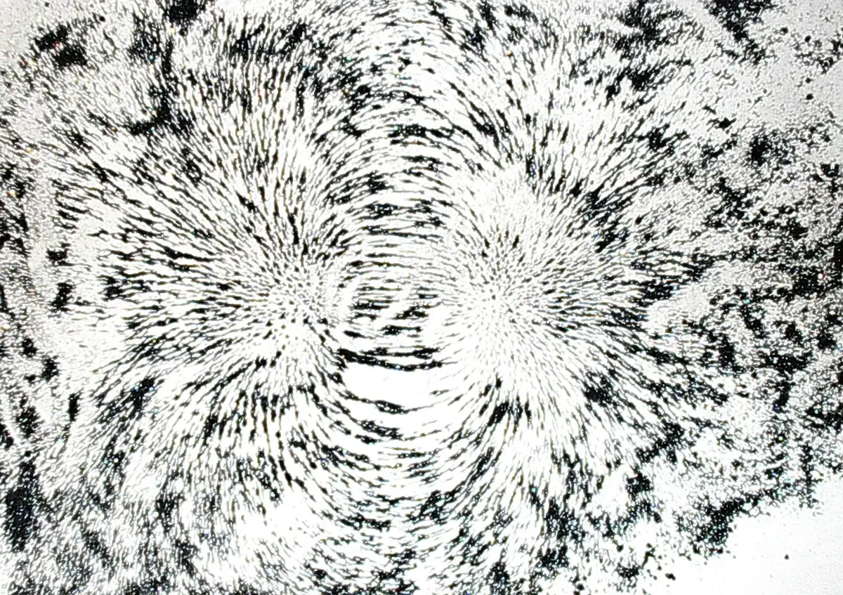
Every magnetic field can be drawn with magnetic lines of force (field lines). Their shape depends on what makes the field.
A single circular loop of wire carrying a current has a field like a very short solenoid: the lines circle round each side of the wire and pass straight through the middle of the loop.
Where the field is strong, the lines are drawn close together; where it is weak, they are far apart. Now imagine holding a small card in the field. Count how many lines pass through it. That number tells you how much magnetic field passes through the card.
The total number of magnetic lines of force passing through a surface is called the magnetic flux through it. It is written Φ (the Greek letter phi), and its SI unit is the weber (Wb), named after the German physicist Wilhelm Eduard Weber.
Where the lines are dense, the flux through a given area is strong; where they are sparse, it is weak. Around a bar magnet, the lines are crowded at the poles, so the flux is strongest at the poles and weakest at the middle.
Motor effect
A current makes a magnetic field. So what happens when a wire carrying a current is placed in the field of another magnet? The two fields push on each other, and the wire moves.
When a current-carrying wire is placed in a magnetic field, a force acts on it and it moves. This production of motion is called the motor effect. The circular field around the wire and the straight field of the magnet add together on one side of the wire and cancel on the other; the wire is pushed from the strong side to the weak side.
The electric motor
A wire that jumps once isn’t very useful. A motor turns the push into a steady spin. Its coil (the rotor) is made by winding insulated wire around a soft iron core, and it sits between two opposite magnetic poles.
When a current flows in the coil, the two long sides of the coil carry current in opposite directions. So one side is pushed up and the other down, and the coil turns. After half a turn, the sides have swapped places, and the push would turn it back. To stop that, the current in the coil must reverse every half turn:
- In a d.c. motor (a toy car, a cooling fan in a computer), a split-ring commutator and two brushes reverse the current every half turn.
- In an a.c. motor (a ceiling fan, a water pump, a mixer grinder), the a.c. supply itself reverses the current, and so the direction of the coil’s magnetic field, 100 times a second.
Either way, the interaction between the field of the magnet and the field of the coil keeps the coil turning, and the coil turns whatever is fixed to its shaft: fan blades, a pump, the blades of a mixer.
To make a motor turn faster or more strongly:
- increase the number of turns in the coil;
- increase the area of the coil;
- use a stronger magnet;
- wind the coil on a soft iron core;
- (and, of course, pass a larger current).
What job does the split-ring commutator do in a d.c. motor?
Pick an answer to see why.
Electromagnetic induction
In the early 1800s, the only source of current was the voltaic cell, a stack of metal plates in acid. Cells were expensive and soon ran down. In 1831, the English scientist Michael Faraday discovered that when a conducting wire cuts across magnetic field lines, a voltage is produced in the wire, and if the wire is part of a closed circuit, a current flows. This discovery changed the world: almost all the electricity we use today is made this way.
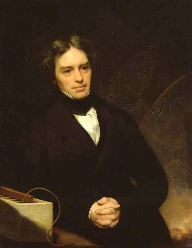
When the magnet moves in or out, the number of field lines passing through the coil, the magnetic flux linked with the coil, keeps changing. A changing flux produces a voltage in the coil. The same happens if the coil is moved, or turned in a magnetic field: as long as the flux through it changes, a voltage is produced. In every case, the work you do moving the magnet or the coil, mechanical energy, is converted into electrical energy.
The production of an electromotive force (e.m.f.), that is, a voltage, in a conductor when the magnetic flux linked with it changes, is called electromagnetic induction. The voltage is called an induced e.m.f., and the current an induced current.
Faraday’s law of electromagnetic induction
The size of the induced voltage depends on three things:
- the strength of the magnet: stronger magnet, more voltage;
- the number of turns in the coil: more turns, more voltage;
- how fast the flux changes: move the magnet slowly and almost no voltage is induced; move it quickly and much more is.
Faraday put this into a law:
Faraday’s law: When there is relative motion between a conductor and a magnet, an e.m.f. is induced in the conductor, and its size is directly proportional to the rate of change of the magnetic flux linked with the conductor.
“Rate of change” means how much the flux changes every second. Double the speed of the magnet and the flux changes twice as fast, so the voltage doubles.
The induced e.m.f. lasts only as long as the flux keeps changing. That is why, to get a steady supply of electricity, a generator keeps a coil turning in a magnetic field, again and again. That is the working principle of a generator, the subject of the next sections.
A magnet sits still inside a coil connected to a galvanometer. What does the meter show?
Pick an answer to see why.
Dynamo and a.c. generator
A dynamo produces current on a small scale, for example to run the light of a bicycle or a motorcycle. An a.c. generator produces it on a large scale, for the electricity that comes to our homes.
The bicycle dynamo
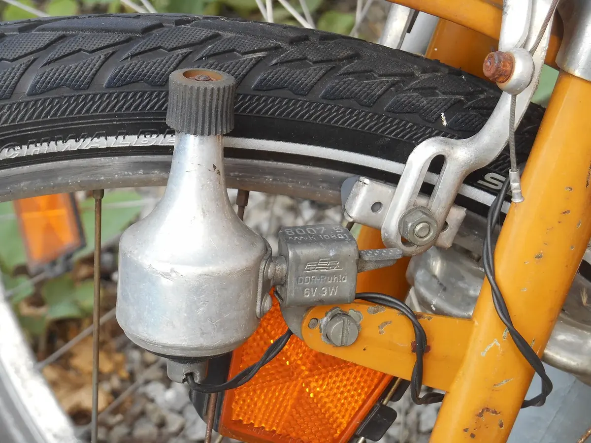
In a bicycle dynamo, a magnet is turned between the arms of an iron core, with a coil of wire wound on it. The cap of the dynamo presses on the tyre; as the wheel turns, friction turns the cap and the magnet with it. The spinning magnet keeps changing the magnetic flux linked with the coil, so an alternating voltage is induced in the coil, and the lamp lights.
The size of the voltage depends on the number of turns in the coil, the strength of the magnet, and the speed of the magnet, that is, the rate at which the flux changes. Ride faster and the lamp glows brighter; slow down and it dims; stop and it goes out.
Large-scale sources of electricity
To make a large amount of electricity, a big coil in a strong magnetic field must be turned very fast, and that takes a lot of energy. Power stations differ only in what turns the turbine, the wheel of blades that spins the generator.
- Hydropower: water stored behind a dam (or taken from a river) flows down a tunnel or pipe at high pressure and spins the turbine.
- Thermal power (coal, diesel): burning coal heats water into high-pressure steam, which spins the turbine. In a diesel plant, a diesel engine turns the generator.
- Nuclear power: works like a coal plant, but the heat to boil the water comes from the fission (splitting) of uranium atoms, under careful control. Nepal has no nuclear power.
- Wind power: the wind turns the blades of a wind turbine, which turns the generator.
(Solar panels are the odd one out: they make d.c. directly from light, with no magnet, coil or turbine.)
Electricity in Nepal
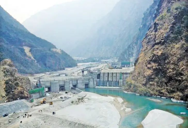
Nearly all of Nepal’s electricity comes from falling water. Rivers that start in the Himalaya drop thousands of meters on their way to the plains, and every meter of that drop can turn a turbine.
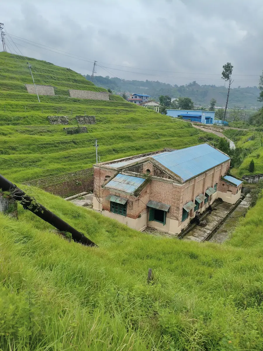
- Nepal’s first hydropower station, at Pharping near Kathmandu, began working in 1911 with a capacity of 500 kW. Its building still stands.
- The largest so far is Upper Tamakoshi in Dolakha (456 MW, completed in 2021).
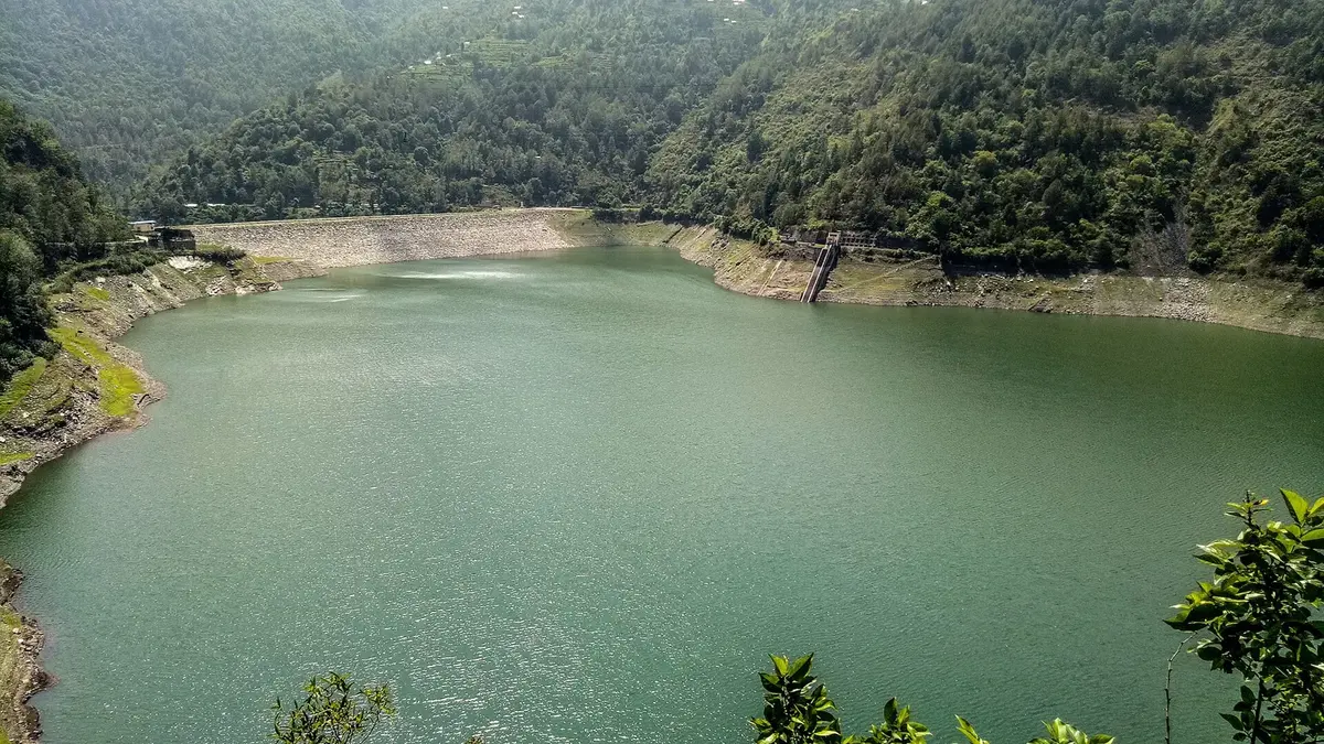
- The Kulekhani project in Makwanpur is Nepal’s only big reservoir (storage) project: it stores monsoon rain to make electricity in the dry season. Most others are run-of-river: they use the river’s flow as it comes, so they make less in winter.
- Nepal’s installed capacity, the power the stations already built can give, has grown fast: about 2,200 MW in 2022 (Nepal Electricity Authority) and about 3,600 MW by March 2025 (the government’s Economic Survey 2024/25), nearly all of it hydropower. The hydropower potential, what Nepal’s rivers could give if fully used, is much bigger: usually estimated at about 83,000 MW in theory, of which about 42,000 MW is thought to be economically worth building. You may see the installed capacity called the “potential”; keep the two apart.
- Nepal has only two small thermal (diesel) plants, at Duhabi (39 MW, multi-fuel) and Hetauda (14.4 MW, diesel), about 53 MW together, and they are hardly used.
- Big projects planned include the Upper Arun (about 1,060 MW), the Dudhkoshi storage project (about 635 MW) and the Uttar Ganga storage project (about 830 MW).
The a.c. generator
An a.c. generator has:
- a strong magnet (in big generators, an electromagnet) to make a magnetic field;
- a rectangular coil of many turns of insulated wire, wound on a soft iron core, which is turned between the poles (it is called the armature);
- two slip rings, one on each end of the coil, which turn with it;
- two carbon brushes that press on the slip rings and carry the current out to the circuit.
As the coil turns, the magnetic flux through it changes continuously, and an e.m.f. is induced in it, in proportion to how fast the flux changes.
- When the plane of the coil is parallel to the field lines (lying flat along them), its sides are cutting the lines fastest: the e.m.f. is at its maximum.
- When the plane of the coil is perpendicular to the field lines (facing them), its sides are moving along the lines, not across them: the e.m.f. is zero for that instant.
- After half a turn, each side of the coil is moving the opposite way through the field, so the e.m.f. reverses.
So each turn of the coil gives one complete cycle of a.c. To make 50 Hz, a simple two-pole generator must turn 50 times a second, 3,000 turns a minute. (Big slow water turbines use generators with many pairs of poles instead.)
To get more current from a generator or a dynamo: use more turns in the coil, a stronger magnet, turn the coil faster, and wind it on a soft iron core.
A bicycle’s dynamo lamp gets brighter as you ride faster. Why?
Pick an answer to see why.
Transformer
Look at the label on a mobile phone charger. It might say Input: 100–240 V ~ 50/60 Hz and Output: 5.3 V ⎓ 2.0 A. The socket gives about 230 V, but the phone needs only about 5 V. Something inside the charger brings the voltage down. A microwave oven needs the opposite: about 2,000 V to make its microwaves, and it gets it from 230 V.
A device that increases or decreases the voltage of alternating current is called a transformer.
Production, transmission and distribution
Electricity travels a long way before it reaches you, in three stages.
- Production (generation): the generator in a power station makes a.c. at about 11 kV (11,000 V).
- Transmission: a step-up transformer at the power station raises it to a high voltage, such as 132 kV, 220 kV or even 400 kV, and it is sent across the country on tall towers.
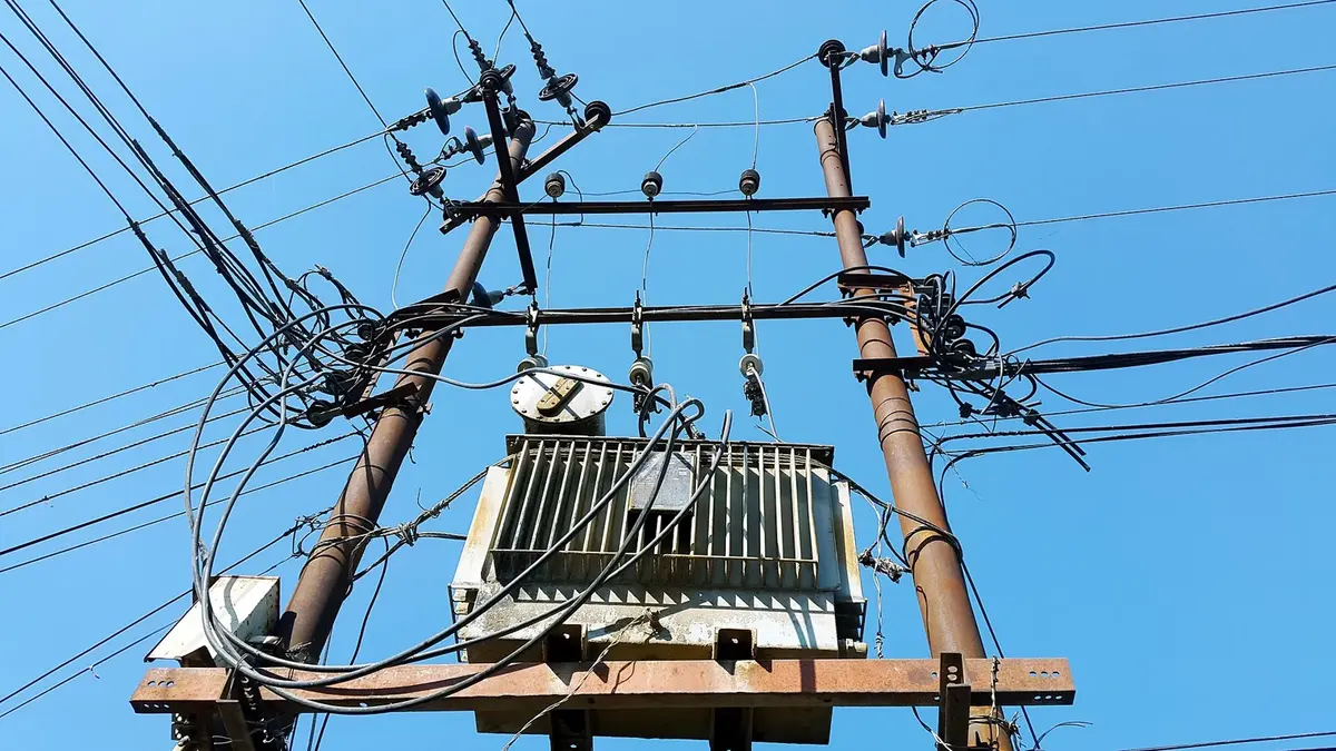
- Distribution: at a substation, step-down transformers lower it to 33 kV and 11 kV for the town’s lines; a small transformer on a pole near your house brings it down to the 230 V your sockets give.
The substation at Dhalkebar in Dhanusha works at 400 kV: it is the Nepal end of the 400 kV line that carries electricity across the border to and from India.
Construction and working of a transformer
A transformer has two coils of insulated copper wire, wound on the same iron core. The coils are not connected to each other.
- The coil that receives the input a.c. is the primary coil. Its number of turns is the primary turns, Nₚ, and its voltage is the primary (input) voltage, Vₚ.
- The coil from which the output is taken is the secondary coil. Its turns are the secondary turns, Nₛ, and its voltage is the secondary (output) voltage, Vₛ.
How can a voltage jump from one coil to the other with no wire between them? When a.c. flows in the primary coil, it makes a magnetic field that keeps changing, 100 times a second. The iron core carries this changing field through the secondary coil. The flux through the secondary keeps changing, so by electromagnetic induction an e.m.f. is induced in it. Inducing an e.m.f. in a coil by changing the current in a neighboring coil is called mutual induction. The transformer works on the principle of mutual induction.
With d.c., the field of the primary coil is steady, so the flux through the secondary doesn’t change and no e.m.f. is induced. A transformer can’t change the voltage of d.c.
Core lamination. The core is not a solid block of iron. It is built from many thin E-, I- and U-shaped iron sheets, each coated with a thin non-conducting layer (varnish or oxide), pressed together and held with nuts and bolts. This is called lamination. The changing field would induce currents inside a solid iron core too, swirling round in it (they are called eddy currents) and heating it up, wasting energy. The insulating layers break up these currents, so the core stays cool and less energy is lost.
Types of transformer
A transformer raises or lowers the voltage depending on the numbers of turns in its two coils.
- Step-down transformer: fewer turns on the secondary than on the primary (Nₛ < Nₚ). The output voltage is lower than the input. With turns in the ratio 2 : 1, 220 V in gives 110 V out. Used in phone chargers, adaptors, door bells, and the transformers on poles.
- Step-up transformer: more turns on the secondary (Nₛ > Nₚ). The output voltage is higher. With turns 1 : 2, 110 V in gives 220 V out. Used at power stations before transmission, in microwave ovens, in X-ray machines, and in the old picture-tube TVs.
The transformer formula
The ratio of the turns equals the ratio of the voltages:
Each turn of wire gets the same share of voltage, so the coil with more turns has more voltage.
Project work
Exercise
1. Choose the correct option
a. Which of the following is a source of a.c.?
Pick an answer to see why.
b. Which scientist discovered the magnetic effect of electric current?
Pick an answer to see why.
c. What is the direction of the magnetic field when a current flows upwards through a straight wire (seen from above)?
Pick an answer to see why.
d. A is a bicycle dynamo and B is a battery torch. Which statement is true?
Pick an answer to see why.
e. On which principle does a transformer work?
Pick an answer to see why.
f. Which is the transformer formula?
Pick an answer to see why.
2. Differentiate between
a.c. and d.c.
Answer
| Alternating current (a.c.) | Direct current (d.c.) |
|---|---|
| Its direction changes again and again. | It flows in one direction only. |
| Its size changes continuously. | Its size stays constant. |
| It has a frequency (50 Hz in Nepal). | Its frequency is zero. |
| Made by dynamos and a.c. generators. | Made by cells, batteries and solar panels. |
| Its voltage can be changed by a transformer. | Its voltage can’t be changed by a transformer. |
Dynamo and generator
Answer
| Dynamo | Generator |
|---|---|
| Produces electricity on a small scale. | Produces electricity on a large scale. |
| Usually the magnet turns and the coil stays still. | In a simple generator the coil turns between the poles of a magnet (big ones turn an electromagnet inside fixed coils). |
| Turned by a bicycle or motorbike wheel. | Turned by a turbine (water, steam, wind) or an engine. |
| e.g. the lamp dynamo of a bicycle | e.g. the generators of a hydropower station |
Motor and generator
Answer
| Motor | Generator |
|---|---|
| Changes electrical energy into mechanical energy (motion). | Changes mechanical energy into electrical energy. |
| Works on the motor effect: a current in a magnetic field feels a force. | Works on electromagnetic induction: a changing flux induces an e.m.f. |
| A current is sent in; the coil turns. | The coil is turned; a current comes out. |
| e.g. fan, water pump | e.g. dynamo, power-station generator |
Step-up transformer and step-down transformer
Answer
| Step-up transformer | Step-down transformer |
|---|---|
| Increases the a.c. voltage. | Decreases the a.c. voltage. |
| More turns on the secondary than the primary (Nₛ > Nₚ). | Fewer turns on the secondary (Nₛ < Nₚ). |
| Output current is smaller than input current. | Output current is larger than input current. |
| Used at power stations, in microwave ovens. | Used in chargers, adaptors, substations, pole transformers. |
3. Give reasons
When a ceiling fan is connected to the circuit of a solar panel, the fan does not rotate.
Answer
A solar panel gives d.c. at a low voltage, but a ceiling fan has an a.c. motor made for about 230 V. Its motor needs a current that keeps reversing to keep turning, and a steady d.c. can’t do that. To run it from a solar panel you need a battery and an inverter (or a fan made for d.c.).
When a magnetic compass is placed near a circuit in which a current is flowing, its needle deflects.
Answer
An electric current produces a magnetic field around the wire (the magnetic effect of current). This field acts on the magnetic needle of the compass and turns it.
An electromagnet is used in an electric bell.
Answer
The bell needs a magnet that can be switched on and off quickly and repeatedly. An electromagnet attracts the iron arm and hammer only while current flows; when the arm moves, it breaks the circuit, the magnetism disappears, the arm springs back and closes the circuit again. This happens many times a second and makes the hammer strike the gong again and again. A permanent magnet could not be switched off.
The numbers of primary and secondary turns of a transformer are not the same.
Answer
The output voltage depends on the turns ratio: . If the turns were equal, the output voltage would equal the input and the transformer would do nothing. To step the voltage up, the secondary has more turns; to step it down, fewer.
The core of a transformer is laminated.
Answer
The changing magnetic field induces currents in the iron core itself (eddy currents), which heat the core and waste energy. Making the core from thin iron sheets insulated from each other breaks up these currents, so less heat is produced and less energy is lost.
Transformers are used in mobile chargers.
Answer
The mains supply is about 230 V a.c., but a phone battery is charged at about 5 V. A step-down transformer in the charger lowers the voltage (a rectifier then turns it into d.c.). Connected straight to 230 V, the phone would be destroyed.
4. Answer the following questions
The frequency of a.c. in our country is 50 Hz. What does it mean?
Answer
The alternating current completes 50 cycles every second. Each cycle takes 1/50 s = 0.02 s, and since the current reverses twice in each cycle, it changes direction 100 times every second.
Draw the current–time graphs of direct current and alternating current.
Answer
See Figure 11.3. For d.c., draw a horizontal straight line above the time axis (the current stays the same, e.g. 4 A). For a.c., draw a smooth wave that rises from zero to a maximum (e.g. +5 A), falls through zero to the same size in the negative direction (−5 A), and returns to zero: one cycle. Label the axes current (A) and time (s).
Draw the magnetic field lines around a current-carrying straight wire and a solenoid.
Answer
For a straight wire: concentric circles around the wire, closer together near it, with arrows showing the direction given by the right-hand thumb rule (see Figure 11.7). For a solenoid: straight parallel lines inside, curving round outside from the north end to the south end like a bar magnet (see Figure 11.8).
Explain the following rules.
- i.Maxwell’s right-hand thumb rule, for the direction of the magnetic field around a straight current-carrying wire.
- ii.Maxwell’s right-hand grip rule, for the direction of the field lines around a solenoid.
Answer
- i.If a straight current-carrying wire is gripped in the right hand with the thumb pointing in the direction of the current, the curled fingers show the direction of the magnetic field lines around the wire.
- ii.If a solenoid is held in the right hand with the fingers curled in the direction of the current in its turns, the thumb points to the solenoid’s north pole.
What is the magnetic effect of current?
Answer
The production of a magnetic field around a conductor when an electric current flows through it. The direction of the field depends on the direction of the current. It was discovered by Oersted in 1820.
Define magnetic flux.
Answer
Magnetic flux through a surface is the total number of magnetic lines of force passing through it. It measures how much magnetic field passes through an area. Its symbol is Φ and its SI unit is the weber (Wb).
How can the magnetic field around a straight current-carrying wire be shown using iron filings, cardboard and a straight wire?
Answer
Pass a straight thick wire vertically through the middle of a piece of cardboard held horizontally. Connect the wire to a cell (or two) and a switch. Sprinkle fine iron filings evenly on the cardboard. Switch the current on and tap the cardboard gently. The filings arrange themselves in concentric circles around the wire, showing that the magnetic field lines are circles centered on the wire. Switch off soon, as the circuit has no resistance and the wire heats up.
Draw the magnetic field developed around a straight current-carrying wire.
Answer
Draw the wire as a vertical line (or, seen from above, a dot in a circle), with several concentric circles around it, spaced more widely as they go outwards. Mark the current direction on the wire and arrows on the circles using the right-hand thumb rule: anticlockwise (seen from above) for a current going up. See Figure 11.7.
What is a solenoid? Draw a picture showing the magnetic field around a solenoid.
Answer
A solenoid is a long cylindrical coil of many turns of insulated wire. When a current flows through it, it behaves like a bar magnet. Draw the coil, with straight parallel field lines inside it and lines curving outside from one end (N) round to the other end (S), as in Figure 11.8.
Write two uses of a solenoid.
Answer
- To make electromagnets (with a soft iron core), used in electric bells, cranes and relays.
- In loudspeakers and earphones, and in solenoid valves and door locks that are opened by switching on a current. (Also: in transformers, induction cooktops and MRI machines.)
Which effects are shown in the figures? (Left: a straight wire between the N and S poles of two magnets, with an arrow showing it moves. Right: a simple motor made of a coil resting on two paper clips above a magnet on a dry cell.)
Answer
Both show the motor effect: a current-carrying conductor in a magnetic field experiences a force and moves. (If, in the left figure, the wire were moved by hand and connected to a galvanometer instead of a cell, it would show electromagnetic induction: a moving wire cutting field lines has a voltage induced in it.)
A simple electric motor made with a coil, paper clips, a dry cell and a permanent magnet is shown. Explain how it works, based on the motor effect.
Answer
The paper clips hold the coil and connect its ends to the terminals of the dry cell, so a current flows through the coil. The current makes the coil a small electromagnet, and it lies in the field of the permanent magnet below. The two fields interact (the motor effect), so a force acts on the coil and it turns. One end of the coil wire has its insulation scraped off only on one half, so the current flows only during half of each turn; during the other half, the coil coasts round on its momentum. In this way the push always acts in the same turning direction, and the coil keeps spinning.
What is electromagnetic induction?
Answer
The production of an e.m.f. (voltage) in a conductor when the magnetic flux linked with it changes, for example when a magnet moves in or out of a coil, or a coil turns in a magnetic field. If the circuit is closed, an induced current flows.
A bar magnet and a solenoid connected to a galvanometer are shown. What happens:
- i.as the magnet is slowly introduced into the solenoid;
- ii.as it is introduced rapidly;
- iii.when it is held stationary inside;
- iv.when it is pulled quickly out?
Answer
- i.The galvanometer needle moves a little to one side: a small current is induced, because the flux changes slowly.
- ii.The needle moves further to the same side: the flux changes faster, so a larger e.m.f. is induced.
- iii.The needle returns to zero: the flux doesn’t change, so nothing is induced.
- iv.The needle moves a large amount to the opposite side: the flux is decreasing quickly, so a large current flows in the opposite direction.
State Faraday’s law of electromagnetic induction.
Answer
When there is relative motion between a conductor and a magnet, an e.m.f. is induced in the conductor, and its size is directly proportional to the rate of change of the magnetic flux linked with the conductor.
A bulb connected to a dynamo on a bicycle tyre does not glow steadily: it was bright, dimmed, and went off when the cycle stopped. Explain.
Answer
The dynamo’s magnet is turned by the tyre. The induced e.m.f. is proportional to the rate of change of flux, that is, to how fast the magnet spins, which depends on the bicycle’s speed. Riding fast, the magnet spins fast and the bulb is bright; slowing down, the e.m.f. falls and the bulb dims; when the cycle stops, the magnet stops, the flux no longer changes, no e.m.f. is induced and the bulb goes off. A dynamo has no battery to store energy.
Write two ways to increase the current produced by a dynamo.
Answer
Any two of:
- 1.increase the number of turns in the coil;
- 2.use a stronger magnet;
- 3.turn the magnet (or coil) faster;
- 4.wind the coil on a soft iron core.
Prepare a research report on any two sources of electricity in Nepal (for example a hydropower station and a solar power plant), with their capacity, the type of electricity produced, and transmission.
A sample report
- Upper Tamakoshi Hydroelectric Project, Dolakha. Capacity 456 MW (six units of 76 MW), completed in 2021, the largest in Nepal. It is a run-of-river project: water from the Tamakoshi River is diverted at a dam into an 8 km headrace tunnel and falls about 820 m to an underground powerhouse. It produces a.c.; the voltage is stepped up and sent on a 220 kV line to the national grid.
- Nuwakot (Devighat area) Solar Farm, Nuwakot. NEA’s first large grid-connected solar plant, with a capacity of 25 MW, connected to the grid in 2022. Solar panels produce d.c.; inverters turn it into a.c., and transformers step it up to join the grid. It makes electricity only in daylight, and most in the dry season, when the rivers are low: it complements hydropower nicely.
(Check the figures for your own report with the Nepal Electricity Authority’s annual report, which is free online; figures change every year.)
What is a transformer?
Answer
A transformer is a device that increases or decreases the voltage of alternating current. It has two coils of insulated wire (primary and secondary) wound on a laminated iron core, and works on the principle of mutual induction.
In the figure, electricity from a power station passes through transformer J, along power cables on towers, and then through transformer K to the consumer. Name the types of transformers J and K.
Answer
J (at the power station) is a step-up transformer: it raises the voltage so the electricity can be sent over long distances with little loss. K (near the consumer) is a step-down transformer: it lowers the voltage to the safe 230 V used at home. See Figure 11.24.
Draw the block diagrams of a step-up and a step-down transformer, and write two uses of each.
Answer
See Figure 11.27: draw the iron core as a rectangle, with the primary coil on one side and the secondary on the other; for step-up, draw more turns on the secondary; for step-down, fewer.
Uses of a step-up transformer:
- 1.at power stations, to raise the voltage for transmission;
- 2.in microwave ovens (about 2,000 V for the magnetron). Also in X-ray machines.
Uses of a step-down transformer:
- 1.in mobile and laptop chargers and adaptors;
- 2.at substations and on electric poles, to bring the voltage down to 230 V for homes. Also in door bells.
5. Solve these problems
To charge a 20 V laptop, a charger with 550 primary turns is connected to a 220 V a.c. supply. Calculate the number of secondary turns.
Answer
Nₚ = 550, Vₚ = 220 V, Vₛ = 20 V, Nₛ = ?
The secondary has 50 turns.
The number of secondary turns of the transformer in a microwave oven is 10 times the number of primary turns. If it is connected to 220 V, what is the secondary voltage?
Answer
Nₛ = 10 Nₚ, so Nₚ/Nₛ = 1/10. Vₚ = 220 V.
The secondary voltage is 2,200 V (a step-up transformer).
The ratio of primary to secondary turns of a transformer is 22 : 1. If an adaptor with this transformer is connected to 220 V, what is the output voltage?
Answer
Nₚ/Nₛ = 22/1, Vₚ = 220 V.
The output voltage is 10 V (a step-down transformer).
Worksheet: Electricity and Magnetism: currents, fields and motors (PDF, 4 pages)
Worksheet: Electricity and Magnetism: induction, generators and transformers (PDF, 4 pages)
Practice every question in the book, and keep track of the ones you miss →