
A street light, a phone charger and a car’s wiring are all just loops of wire, cells and resistors, yet some of them can’t be untangled into “this pair in series, that pair in parallel”. Two batteries side by side, a bridge of four resistors with a meter across its middle: Ohm’s law alone gets stuck. Two simple rules from a 21-year-old student in 1845 solve every one of them.
This unit gives you those rules, Kirchhoff’s laws, and then the instruments built on them: the Wheatstone bridge and meter bridge, which measure a resistance by finding where a meter reads nothing; the potentiometer, which measures an e.m.f. without taking any current from the cell; and the way a delicate galvanometer becomes an ammeter or a voltmeter. It ends with superconductors, which have no resistance at all, and Joule’s laws of the heat a current makes.
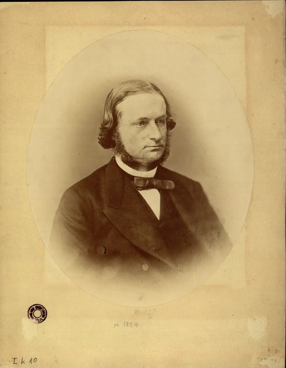
Gustav Kirchhoff was still a student at Königsberg when, in 1845, he wrote down the two circuit laws that carry his name, to work out the currents in any network of wires. He went on to work with the chemist Robert Bunsen at Heidelberg. Together they found that every element, heated in a flame, gives out its own set of colors, and invented spectrum analysis: by passing sunlight through a prism and finding the dark lines of sodium, iron and other elements in it, they could say what the Sun is made of, without going there. He also built on the work of Georg Simon Ohm, extending his laws to currents that spread through solid, three-dimensional conductors, and coined the term “black body” for an ideal absorber of radiation, the start of the road to quantum physics.
Ohm’s law is enough for a simple circuit: if you can see which resistances are in series and which in parallel, you can find the effective resistance, then the current, then every p.d. But a circuit with more than one source of e.m.f., or with resistors joined in a way that is neither series nor parallel, can’t be reduced like that. For these, Kirchhoff’s two laws give enough equations to find every current.
14.1 Kirchhoff’s laws
Kirchhoff’s laws are not limited to direct current (DC). They hold at every instant in alternating current (AC) circuits too, including circuits with capacitors and inductors (whose “resistances” are then the complex impedances of Unit 19). There are two laws: one about currents at a junction, one about voltages round a loop.
Kirchhoff’s first law (the junction rule)
A junction (or node) is a point where three or more wires meet. Charge can’t pile up at a junction, and it can’t be made or destroyed there: every coulomb that flows in each second must flow out in the same second. Charge per second is current, so:
Kirchhoff’s first law: the algebraic sum of the currents meeting at a junction in a circuit is zero.
Sign convention:
- i.a current flowing towards the junction is taken as positive;
- ii.a current flowing away from the junction is taken as negative.
At the junction O in Figure 14.2, the currents I₁, I₂ and I₃ flow towards O, so they are positive, and I₄ and I₅ flow away from O, so they are negative. By Kirchhoff’s first law,
The total current flowing into a junction equals the total current flowing out of it. The law follows from the conservation of charge, and it is also called the junction rule or Kirchhoff’s current law (KCL).
It is the same as traffic at a chowk: if cars never park or vanish at the crossing, as many must leave each minute as arrive.
At a junction, 3 A and 5 A flow in along two wires, and 2 A flows out along a third. What flows in the fourth wire?
Pick an answer to see why.
Kirchhoff’s second law (the loop rule)
Kirchhoff’s second law: in any closed loop of a circuit, the algebraic sum of the e.m.f.s equals the algebraic sum of the potential drops (the products IR) round the loop.
Put another way, if you go once round any closed loop, adding up every rise and fall of potential, the total change in potential is zero:
This is the loop rule, also called the mesh rule or Kirchhoff’s voltage law (KVL). Why must it hold? The potential at a point has one definite value. If you set off from a point, walk round a loop and come back to the same point, you must find the same potential you started with, so the rises and falls on the way must cancel. In energy terms, a coulomb that goes once round a loop gains energy in the cells (their e.m.f.s) and gives up exactly the same energy in the resistors (the IR drops). So the second law follows from the conservation of energy, and it holds because the electrostatic force is conservative: the work it does round any closed path is zero.
It is like walking round Bhaktapur’s Durbar Square: whatever steps you climb and descend on the way, when you are back at the spot you started from, your total change in height is zero.
Sign convention for the loop rule
Choose a direction to go round the loop (clockwise or anticlockwise; either works), and then:
- i.Going through a cell from its negative to its positive terminal, the potential rises: its e.m.f. is taken as positive, +E.
- ii.Going through a cell from its positive to its negative terminal, the potential falls: its e.m.f. is taken as negative, −E.
- iii.Going through a resistor in the direction of the current, the potential falls (current flows from high potential to low): the product IR is taken as negative, −IR.
- iv.Going through a resistor against the current, the potential rises: +IR.
The direction you choose for each unknown current doesn’t have to be right. Guess it, and mark it on the diagram. If the answer comes out negative, the current flows the other way, with the same size.
Kirchhoff’s first and second laws follow from the conservation of, respectively:
Pick an answer to see why.
Using the laws
To solve any circuit:
- Mark a current, with a direction, in each branch (a branch is a path between two junctions). Use the junction rule at once to save unknowns: if I₁ and I₂ meet, the next branch carries I₁ + I₂.
- Choose enough loops to give as many equations as there are unknown currents left, each loop going through at least one branch not used before.
- Go round each loop with the sign convention, and set the sum to zero.
- Solve the equations together. A negative answer means that current flows opposite to the arrow.
14.2 Wheatstone bridge principle from Kirchhoff’s laws
A Wheatstone bridge is a circuit for measuring an unknown resistance X very accurately. It has four resistances joined in a ring ABCD (Figure 14.8): two fixed, known resistances P and Q (the ratio arms, usually of manganin or constantan, whose resistance hardly changes with temperature), a variable known resistance R, and the unknown X. A cell is connected between A and C, and a sensitive galvanometer G between B and D, “bridging” the two paths.
R is adjusted until the galvanometer shows no deflection: the null point. Then B and D are at the same potential, and
This is the principle of the Wheatstone bridge. Here is why, from Kirchhoff’s laws.
Let I₁, I₃, I₄ and I₂ be the currents in P, Q, R and X, and Ig the current in the galvanometer (resistance G), from B to D.
Step 1. Loop ABDA (second law), traveling A → B → D → A: with I₁ through P, with Ig through G, then against I₂ through X:
Step 2. Loop BCDB, traveling B → C → D → B: with I₃ through Q, against I₄ through R, against Ig through G:
Step 3. Junction B (first law): I₁ in, Ig and I₃ out:
Step 4. Junction D: Ig and I₂ in, I₄ out:
Step 5. Balance. R is adjusted until the galvanometer shows no deflection: . Then the four equations become
Step 6. Divide. Using and in (14.6): . Dividing (14.5) by this,
So : knowing P, Q and R, the unknown X is found.
A memory aid: at balance, the ratio of the two resistances on one side of the galvanometer equals the ratio on the other side, taken in the same order from the cell’s end A.
In a balanced Wheatstone bridge, the galvanometer and the cell are interchanged. The galvanometer now:
Pick an answer to see why.
14.3 Meter bridge
The meter bridge (also called the slide wire bridge) is the simplest practical Wheatstone bridge. It works on the principle of the Wheatstone bridge: two of the four arms are the two parts of one uniform wire, divided by a sliding contact.
Construction (Figure 14.9). A constantan (or manganin) wire exactly 1 m long and of uniform cross-section is stretched along a wooden board between two thick copper strips at A and C. A meter scale is fixed on the board beside the wire. A third copper strip between them leaves two gaps: a resistance box R is connected across one gap and the unknown resistance X across the other. One terminal of a sensitive galvanometer is joined to the middle strip (point B), and the other to a jockey, a knife-edge contact that can be slid along the wire and pressed on it at any point J. A cell and key are connected across the ends of the wire.
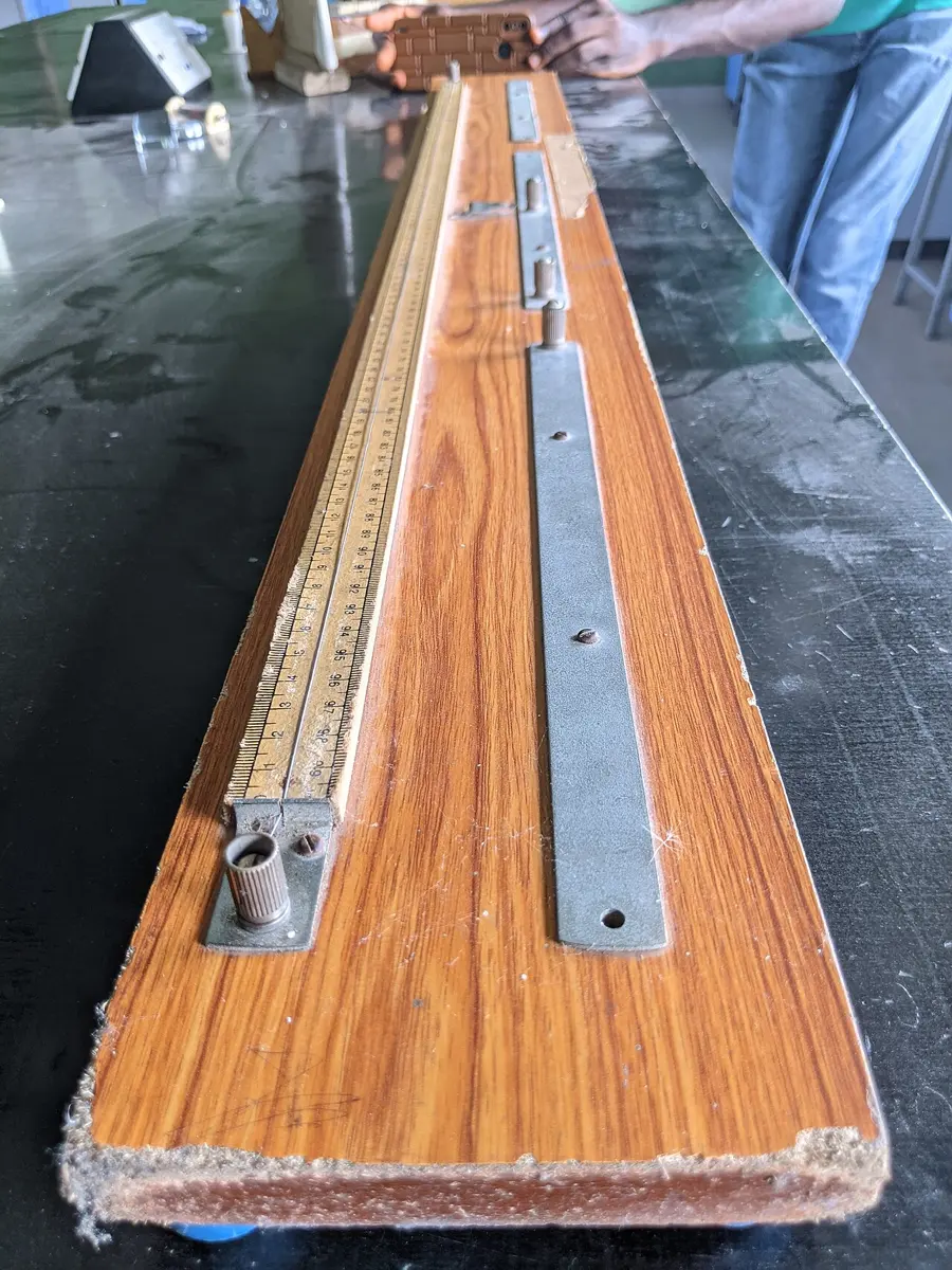
The circuit is exactly that of a Wheatstone bridge: the part of the wire from A to the jockey is one arm (call its resistance P), and the part from the jockey to C is another (Q); X and R are the other two. The jockey is moved until the galvanometer shows no deflection.
To measure an unknown resistance
Suppose the balance point J is at a distance l (in cm) from the end A, so that JC = (100 − l) cm. The wire is uniform, so the resistance of each part is proportional to its length:
From the principle of the Wheatstone bridge, , so
Knowing R and l, X is found. The same circuit can compare two resistances: put one in each gap, and their ratio is .
The result is most accurate when the balance point is near the middle of the wire: a small error in reading l then makes the smallest error in X. So R is chosen close to the expected value of X.
In a meter bridge with 5 Ω in the left gap and 15 Ω in the right gap, the balance point is:
Pick an answer to see why.
14.4 Potentiometer
A potentiometer is an instrument for measuring the e.m.f. of a cell, comparing the e.m.f.s of two cells and finding the internal resistance of a cell. A voltmeter draws some current from the cell it measures, and so reads the terminal p.d., which is less than the e.m.f. by Ir. A potentiometer, at its balance point, draws no current from the cell, so it measures the e.m.f. itself.
Construction. A long wire of uniform cross-section, usually 10 m of constantan or manganin, is stretched on a wooden board in ten lengths of 100 cm each, side by side, joined at their ends by thick copper strips, with a meter scale beside them. A battery (the driver cell), a key, an ammeter and a rheostat are connected across the ends A and B of the whole wire, so that a steady current flows through it; the rheostat keeps the current constant and sets its value. In diagrams the wire is drawn as one straight line AB.
Principle
When a constant current flows through a wire of uniform cross-section, the potential difference across any length of the wire is directly proportional to that length.
Proof. Let V be the p.d. across a length l of the wire, of resistance R, when a current I flows. By Ohm’s law, . The resistance of the length is , where ρ is the resistivity of the material and A the area of cross-section. So
With a constant current I and a uniform wire (ρ and A the same everywhere), is a constant, k:
The constant is the potential gradient: the fall of potential per unit length of the wire, in V/m or V/cm.
How the balance point measures an e.m.f.
The test cell is connected with its + terminal to A, the same end as the driver cell’s + terminal, and its other terminal through the galvanometer to the jockey (Figure 14.12). Then the cell’s e.m.f. E and the p.d. along the wire from A to J push against each other in the galvanometer’s loop:
- if J is too near A, the p.d. AJ is less than E, and the cell pushes a current one way through G;
- if J is too far, the p.d. AJ is more than E, and current flows the other way;
- at one point, the balance point (or null point), the p.d. AJ exactly equals E, and no current flows through G, or through the cell.
At balance the cell gives no current, so there is no drop across its internal resistance: the p.d. it balances is its full e.m.f.
Applications of the potentiometer
1. To compare the e.m.f.s of two cells
The two cells E₁ and E₂ have their + terminals joined to A, and their − terminals to the two outer terminals of a two-way key, whose middle terminal is connected through the galvanometer G to the jockey (Figure 14.13). A steady current is kept in the wire by the driver cell (of e.m.f. greater than either), with an ammeter, a rheostat and a one-way key.
First the key is set to connect E₁ alone. The jockey is slid along the wire until the galvanometer shows no deflection, at a balance length from A. By the principle of the potentiometer,
where k is the potential gradient. Then the key is set to connect E₂ alone, and the balance length is :
The current, and so k, is the same both times (the rheostat is not touched). Dividing,
If one cell is a standard cell of known e.m.f., the other e.m.f. is found.
2. To measure the internal resistance of a cell
The cell, of e.m.f. E and internal resistance r, is connected as a test cell (+ terminal to A, − terminal through G to the jockey), and a resistance box R with a key K₂ is connected across its terminals (Figure 14.14).
K₂ open. The cell gives no current (at balance), so the p.d. balanced is its e.m.f. The balance length is :
K₂ closed. Now the cell drives a current I through R, and the p.d. across its terminals, , is less than E. The balance length is shorter, :
The internal resistance. The cell’s current flows through r and R in series: , while . Dividing,
Using (14.11) and (14.12), , so
Knowing , and R, the internal resistance is found.
Sensitivity, and other uses
A potentiometer is more sensitive when a small change in p.d. moves the balance point a long way, that is, when its potential gradient is small. It can be made smaller by using a longer wire (that is why the wire is 10 m long), or by reducing the current in the wire (more resistance from the rheostat). The potentiometer is also used to calibrate voltmeters and ammeters, and to measure very small e.m.f.s such as those of thermocouples (Unit 15). Because it takes no current at balance, it behaves like an ideal voltmeter, one of infinite resistance.
14.5 Conversion of galvanometer into ammeter and voltmeter
Galvanometer
A galvanometer is an instrument for detecting, and measuring, small electric currents. It works by the motor effect: a current through a coil in a magnetic field makes the coil turn (Unit 16). It may be a moving-magnet galvanometer or a moving-coil galvanometer; in the laboratory the usual one is the Weston-type moving-coil galvanometer, also called the pointer-type galvanometer, whose pointer’s deflection is proportional to the current. A typical one gives full-scale deflection for a current Ig of a few milliamperes or less, and has a coil resistance G of a few ohms to a hundred ohms.
On its own a galvanometer can’t carry a large current (its fine coil would overheat) or measure a large p.d. With a suitable resistor added, it becomes an ammeter or a voltmeter.
Shunt
A shunt is a low resistance connected in parallel with a galvanometer. It carries most of the current in the circuit, leaving only a small, definite part to flow through the galvanometer.
Uses of a shunt:
- i.A moving-coil galvanometer is very sensitive and is damaged by a large current. A shunt protects it: only a small part of the total current passes through the galvanometer.
- ii.A shunt converts a galvanometer into an ammeter.
- iii.A shunt connected across any resistance in a circuit lowers the total resistance, and so increases the current in the circuit.
Conversion of a galvanometer into an ammeter
An ammeter measures the current in a circuit, so it is connected in series, and it must have a low resistance so as not to change that current. Suppose a galvanometer of resistance G gives full-scale deflection with a current Ig. To make it an ammeter reading 0 to I, a shunt S is connected in parallel with it (Figure 14.17a), chosen so that when a current I flows into the combination, only Ig flows through the galvanometer and the rest, , through the shunt.
G and S are in parallel, so the p.d. across them is the same:
Knowing Ig, I and G, S is calculated; with this shunt, the galvanometer is an ammeter of range 0 to I. The resistance of the whole ammeter, , is less than S: very small, as an ammeter’s should be.
Conversion of a galvanometer into a voltmeter
A voltmeter measures the p.d. between two points, so it is connected in parallel with them, and it must have a high resistance so as to take as little current as possible. To make a galvanometer a voltmeter reading 0 to V, a high resistance R (sometimes called a multiplier) is connected in series with it (Figure 14.17b), chosen so that a p.d. V across the combination drives exactly the full-scale current Ig through it:
Knowing V, Ig and G, R is found; with it in series, the galvanometer is a voltmeter of range 0 to V. Its resistance, G + R, is large.
The resistance of an ideal ammeter and of an ideal voltmeter are, respectively:
Pick an answer to see why.
14.6 Superconductivity
Cool a metal and its resistance falls, because its vibrating ions get in the way of the electrons less. In 1911 the Dutch physicist Heike Kamerlingh Onnes, who three years earlier had been the first to liquefy helium (at 4.2 K, −269 °C), cooled mercury with it and saw something no one expected: at 4.2 K its resistance did not just fall, it vanished, dropping suddenly to zero.
Superconductivity is the property of certain metals, alloys and compounds of losing all electrical resistance below a certain temperature, the critical temperature (or transition temperature) Tc. Below Tc, a current can flow without any resistance, and so without losing any energy as heat.
The critical temperature is different for each material: mercury 4.2 K, lead 7.2 K, niobium 9.2 K; an alloy of plutonium, cobalt and gallium becomes superconducting below 18.5 K. Above Tc the material conducts like an ordinary metal; below it, it is a superconductor. In a famous experiment, a current set going in a ring of superconducting wire, with no battery at all, kept flowing for over two years without any measurable decrease. Research goes on to find a superconductor that works at room temperature; so far, none does.
Applications of superconductors
- Very strong electromagnets: a superconducting coil carries a huge current with no heating. The magnets in MRI scanners in hospitals, including those in Kathmandu, are coils of niobium–titanium wire kept at about 4 K in liquid helium.
- Research: the giant magnets that steer particles round the Large Hadron Collider at CERN, and research in materials science and high-energy particle physics.
- Very fast electronic devices: superconducting circuits switch very fast with almost no power, and are used in very sensitive magnetic sensors (SQUIDs) and in many of today’s quantum computers.
- Transmission of electric power: superconducting cables could carry electricity with no loss; short ones are already in trial use in a few cities, though the cooling is costly.
- Magnetic levitation (maglev) trains: Japan’s superconducting maglev reached a record 603 km/h in 2015.
Perfect conductor
A perfect conductor is an idealized material with zero resistivity (infinite conductivity). Inside it the electric field is zero, so the potential is the same everywhere in it and there is no potential difference between any two of its points; at its surface the tangential electric field is zero.
A superconductor has zero resistance, but it is more than a perfect conductor. A perfect conductor would keep whatever magnetic field was inside it when it lost its resistance (a changing field would drive currents that oppose any change). A superconductor actively pushes the field out, whatever was there before: the Meissner effect.
Meissner effect
The Meissner effect is the expulsion of a magnetic field from a material when it becomes superconducting.
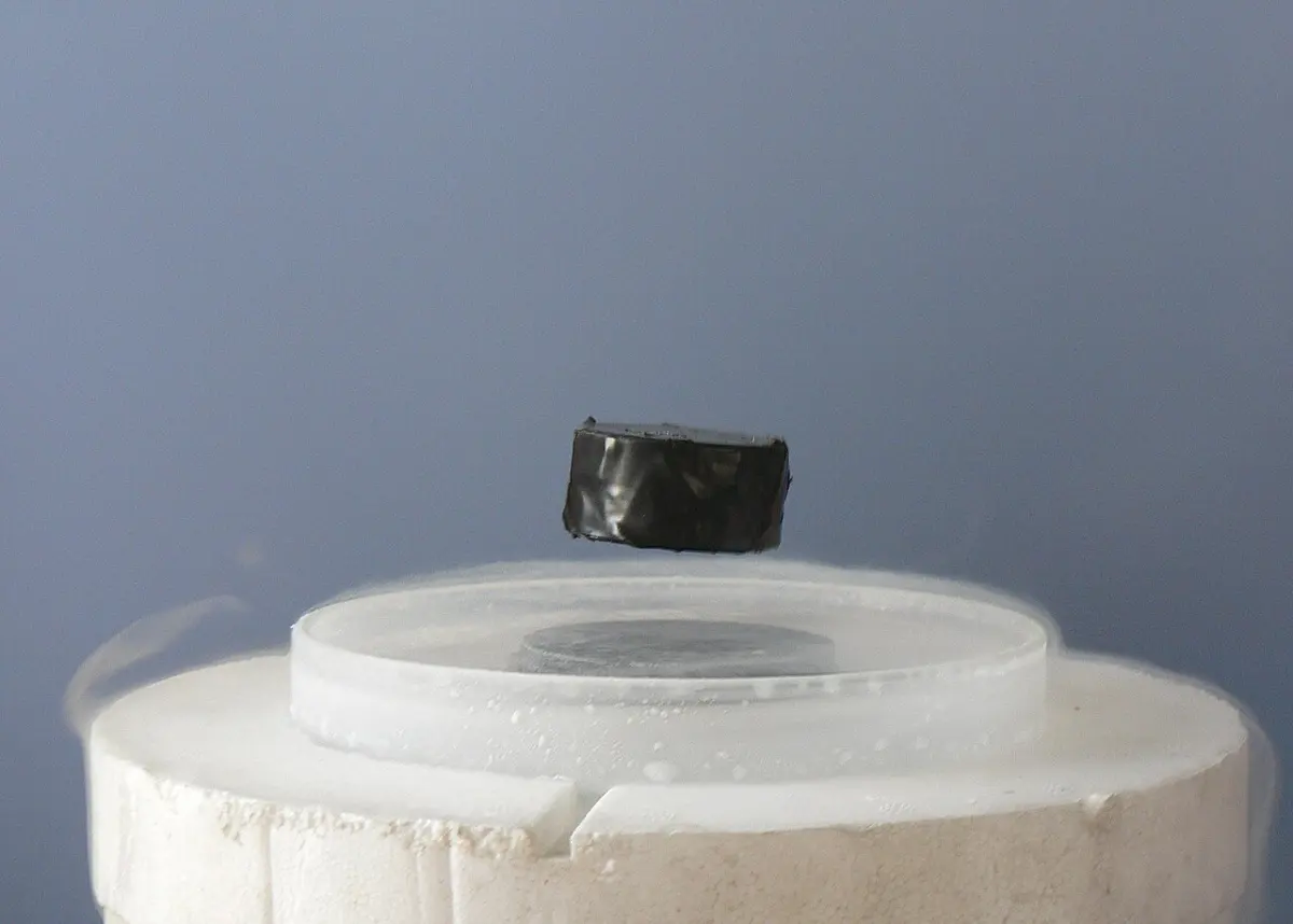
Discovered by Walther Meissner and Robert Ochsenfeld in 1933, it is a key property of superconductors. A material in a magnetic field, above Tc, lets the field pass through it almost unchanged. Cool it below Tc, and it expels the magnetic field from its interior: currents set up in a thin layer at its surface make a field that exactly cancels the applied field inside. Inside, B = 0. A superconductor is a perfect diamagnet (its magnetic susceptibility χ = −1; Unit 17).
Because the field is pushed out, a superconductor repels a magnet. A small magnet placed over a superconductor cooled in liquid nitrogen floats in the air, the most famous demonstration in physics.
Which of these does a superconductor do, and a merely perfect conductor not?
Pick an answer to see why.
14.7 Joule’s laws of heating
In 1841 James Prescott Joule, a brewer’s son from Manchester, measured how the heat a current produces in a wire depends on the current, the wire’s resistance and the time. His results, Joule’s laws of heating, say that the heat H produced in a conductor is:
- i.directly proportional to the square of the current: (R and t kept constant);
- ii.directly proportional to the resistance of the conductor: (I and t kept constant);
- iii.directly proportional to the time for which the current flows: (I and R kept constant).
Combining these, , and in SI units the constant is 1:
with H in joules. This is the electrical energy turned into heat: a charge falls through a p.d. , losing energy .
To give the heat in calories,
where J is Joule’s mechanical equivalent of heat, 4.18 J/cal (4.186 J/cal, more exactly). It is simply a conversion factor: is the energy in joules, and dividing by J gives it in calories.
Variation with resistance. Keeping the current and the time constant, and changing the resistance, the heat produced is found to be proportional to R: a straight line through the origin (Figure 14.23a).
Variation with time. Keeping the current and the resistance constant, the heat produced is proportional to t: a straight line through the origin (b).
Variation with current. Keeping the resistance and the time constant, the heat produced is proportional to I²: a graph of H against I² is a straight line through the origin (c). (Against I itself, it is a parabola: double the current, four times the heat.)
From all three, the heat developed in the resistor is .
Exercise
Choose the correct option
- What is the value of I₄ flowing in the circuit shown?
Pick an answer to see why.
- The statement “In a closed loop of an electric circuit, the algebraic sum of the e.m.f.s is equal to the algebraic sum of the potential drops” is:
Pick an answer to see why.
- Consider two statements: (i) Kirchhoff’s junction law follows from the principle of conservation of charge. (ii) Kirchhoff’s junction law follows from the principle of conservation of the electric field.
Pick an answer to see why.
- If the null point of a potentiometer with a cell of e.m.f. E is at a balance length l on the wire, then:
Pick an answer to see why.
- A length of 650 cm of a potentiometer wire is needed to balance the e.m.f. of a cell. When a resistor of 8 Ω is connected across the cell’s terminals, the balance length is 520 cm. The internal resistance of the cell is:
Pick an answer to see why.
- A galvanometer is connected to the secondary coil of a solenoid. It shows an instantaneous maximum deflection of 7 divisions when the current is started in the primary coil. If the primary coil is now turned through 180° and the current started again, the instantaneous maximum deflection will be:
Pick an answer to see why.
- A resistance of 5 Ω is connected in the left gap of a meter bridge and 15 Ω in the right gap. The balance point is at:
Pick an answer to see why.
- The resistivity of a potentiometer wire is 40 × 10⁻⁸ Ω m and its area of cross-section is 8 × 10⁻⁶ m². If a current of 0.2 A flows through the wire, the potential gradient is:
Pick an answer to see why.
- A potentiometer has a wire 400 cm long, of resistance 10 Ω, connected to a cell of e.m.f. 2 V with negligible internal resistance. The potential difference per unit length of the wire is:
Pick an answer to see why.
- Two cells of e.m.f. 1.25 V and 0.75 V are connected in parallel (+ to +). The effective voltage will be:
The textbook gives the options 0.75, 1.25, 2.00 and 0.50 V, none of which is right, so the book’s options don’t work; the fourth is replaced here.
Pick an answer to see why.
- The instrument for the accurate measurement of the e.m.f. of a cell is:
Pick an answer to see why.
- The internal resistance of an ideal voltmeter is:
Pick an answer to see why.
- A galvanometer of resistance 99 Ω should carry 10 % of the main current. The shunt to be connected in parallel with it is:
Pick an answer to see why.
Answer these questions
- a.State Kirchhoff’s current law and voltage law.
- b.Using Kirchhoff’s laws, find the current in the 2 Ω resistor in Figure 14.25.
- c.Can Kirchhoff’s laws be used for both AC and DC circuits?
Hint
Answer
Figure 14.26 shows a potentiometer with a cell of 2.0 V and internal resistance 0.40 Ω maintaining a potential drop across the resistance wire AB. A standard cell of constant e.m.f. 1.02 V gives the balance point at 67.3 cm of the wire. To make sure very little current is drawn from the standard cell, a very high resistance of 600 kΩ is put in series with it. The standard cell is then replaced by a cell of unknown e.m.f., and the balance point, found the same way, is at 82.3 cm.
- a.What is the e.m.f. of the unknown cell?
- b.What is the purpose of the 600 kΩ resistance?
- c.Is the balance point affected by this high resistance?
- d.Would the method work if the driver cell had an e.m.f. of 1.0 V instead of 2.0 V?
Answer
A student sets up a potentiometer circuit as in Figure 14.27.
- i.State the principle of the potentiometer.
- ii.What is potential gradient? On what factors does the potential gradient of a potentiometer depend?
- iii.The student obtains the balance point at 34.5 cm using a standard cell of e.m.f. 1.50 V. The balance length AC for the test cell is 25.00 cm. Calculate the e.m.f. of the test cell.
The textbook’s figure labels the driver cell 1.5 V and the test cell 5 V, so the book’s numbers don’t work: a 1.5 V driver can’t balance a 5 V cell anywhere on the wire, and the 1.50 V standard only near its far end. The figure here leaves those labels out; the question’s own numbers work.
Answer
- a.State the principle of the potentiometer. Why is a potentiometer also called a voltmeter of infinite resistance?
- b.In a meter bridge experiment (Figure 14.28), the balance point is at J with l = 20 cm.
- i.The values of R and X are doubled and then interchanged. Where is the new balance point?
- ii.If the galvanometer and the battery are interchanged at the balance position, how is the balance point affected?
Answer
- a.State Kirchhoff’s two laws for electrical circuits.
- b.In the meter bridge of Figure 14.29, the null point is 60 cm from A. When a resistance of 5 Ω is connected in series with S, the null point is at 50 cm from A. Find R and S.
Answer
- a.The arrangement of a potentiometer circuit for finding the internal resistance r of a cell is shown in Figure 14.14. Derive an expression for the internal resistance of the cell.
- b.How can you convert a galvanometer into a voltmeter of suitable range?
Answer
- a.What is the principle of the potentiometer?
- b.Why is the potentiometer preferred to a voltmeter for measuring the e.m.f. of a cell?
- c.The e.m.f. of a battery is balanced by 75 cm of a potentiometer wire, and the e.m.f. of a standard cell of 1.02 V by 50 cm of it. Calculate the e.m.f. of the battery.
Answer
Kirchhoff’s laws are very useful in solving complicated circuits.
- a.What is the significance of the first law?
- b.State and explain the second law with a circuit diagram.
- c.Apply these laws to find an unknown resistance.
- d.What is a meter bridge? Name the material used for its wire.
Answer
A student sets up the circuit in Figure 14.30 to measure the e.m.f. of a test cell.
- a.Explain why he can’t find a balance point, and state the change he must make to get one.
- b.State how he would recognize the balance point.
- c.He obtains the balance point at 37.5 cm with a standard cell of e.m.f. 1.50 V, and at 25.0 cm (AB) with the test cell. Calculate the e.m.f. of the test cell.
- d.He could have used an ordinary voltmeter to measure the test cell’s e.m.f. directly, but he argues that this instrument is more precise. Justify his argument.
Answer
- a.Using Kirchhoff’s laws, derive the balance condition of a Wheatstone bridge.
- b.In Figure 14.31, AB is a uniform wire of resistance 15 Ω and length 1 m. With ε₁ = 2 V and ε₂ = 75 mV, the balance point is 30 cm from A. Calculate R (take ε₁’s internal resistance as negligible).
- c.Compare the resistances of a milliammeter, an ammeter and a microammeter.
Answer
- a.Find the terminal potential difference across the cell of e.m.f. 12 V in Figure 14.32.
- b.Explain briefly how a potentiometer can be used to measure the internal resistance of a cell.
- c.Compare the resistances of a microvoltmeter, a voltmeter and a millivoltmeter.
Hint
Answer
- a.State Kirchhoff’s second law.
- b.Two batteries, each of e.m.f. 6.0 V and negligible internal resistance, are connected in series with three resistors as in Figure 14.33. Resistor X has resistance 4.0 Ω and resistor Y 1.5 Ω. The resistance R of the variable resistor is changed until the voltmeter reads zero. Calculate i. the current I in the circuit; ii. the resistance R.
Answer
- a.State Kirchhoff’s second law.
- b.An electric heater has two heating wires, X and Y, connected to a supply of e.m.f. 9.0 V and negligible internal resistance, as in Figure 14.34. X has resistance 2.4 Ω and Y 1.2 Ω. A voltmeter is connected across the wires, and a variable resistor adjusts the power in them. The variable resistor is set so that the voltmeter reads 6.0 V.
- i.Calculate the resistance of the variable resistor.
- ii.Calculate the power dissipated in wire X.
Answer
- a.i. State Kirchhoff’s second law. ii. Kirchhoff’s second law is linked to the conservation of a certain quantity. State it.
- b.The circuit of Figure 14.35 is used to compare potential differences. The uniform resistance wire XY has length 1.00 m and resistance 4.0 Ω. Cell A has e.m.f. 2.0 V and internal resistance 0.50 Ω, and the current through it is I. Cell B has e.m.f. E and internal resistance r. The current through cell B is made zero when the contact J is adjusted so that XJ is 0.90 m. The variable resistor R is set at 2.5 Ω.
- i.Apply Kirchhoff’s second law to the circuit CXYDC to find the current I.
- ii.Calculate the p.d. across the length XJ of the wire.
- iii.Use your answer to ii. to state the value of E.
- iv.State why the internal resistance of cell B is not needed to find E.
Answer
- a.A metal wire of constant resistance is used in an electric heater. So as not to overload the circuit, the supply voltage to the heater is reduced from 230 V to 220 V. Find the percentage reduction in the heater’s power.
- b.A uniform wire AB of length 100 cm is connected across a cell of e.m.f. 1.5 V and negligible internal resistance, as in Figure 14.36. An ammeter of internal resistance 5.0 Ω is connected to the end A of the wire and to a contact C that can be moved along it. Find the ammeter reading with C i. at A; ii. at B.
- c.Using this circuit, the ammeter reading I is recorded for different distances L of C from A; some of the points are plotted in Figure 14.37.
- i.Plot the points for C at A and at B (your answers to b.).
- ii.Draw a line of best fit through all the points, and find the ammeter reading with C at the midpoint of the wire.
- iii.Use your answer to ii. to calculate the p.d. between A and C with C at the midpoint.
- d.Explain why, although C is at the midpoint of AB, your answer to c.iii is not half the e.m.f. of the cell.
Answer
Printable PDFs
- The unit as a book (A5) 33 pages Answers as an A4 booklet, 9 sheets
- Study notes 3 pages
- Worksheet 4 pages Answer key
- Harder practice questions 2 pages Answer key
Quiz yourself: Electricity and Magnetism, Grades 5–12 →
Practice every question in the book, and keep track of the ones you miss →
A companion to your textbook, not a replacement for it: study from the book your school uses, and where the two differ, follow your teacher. Found a mistake? Please tell us.