
Why must you swipe a card through a card reader instead of holding it still in the slot? The magnetic stripe on an old bank card is a row of tiny magnets. Held still, they do nothing to the reader. Swept past the reader’s little coil, their field through the coil changes, and a changing field makes a voltage in the coil: the reader “hears” the stripe only while it moves.
That is electromagnetic induction, and it is how almost all the world’s electricity is made, from Kulekhani to the bicycle dynamo. This unit gives you its two laws (Faraday’s, for the size of the induced e.m.f., and Lenz’s, for its direction), the e.m.f. of a rod sliding through a field and of a coil spinning in one (the a.c. generator), the eddy currents that brake trains and cook food, the self and mutual induction of coils, the energy a coil stores, and the transformer that carries power from a dam to your home.

Electromagnetic induction
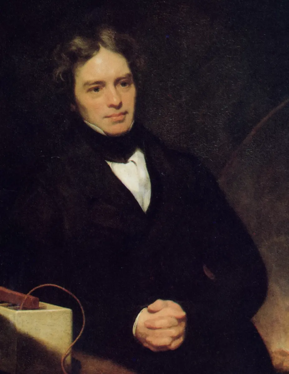
In 1820 Hans Christian Ørsted found that an electric current makes a magnetic field. Scientists then asked the opposite question: can a magnet make a current? Faraday answered it in 1831. A magnet lying still beside a coil does nothing; but moving the magnet towards or away from a closed coil, or moving the coil near the magnet, makes a current flow in the coil.
Electromagnetic induction is the production of an e.m.f. in a conductor, and so of a current in a closed circuit, when the magnetic flux linked with it changes, for example by relative motion between the conductor and a magnetic field. The e.m.f. is called the induced e.m.f. and the current it drives the induced current.
In a power station, magnets move relative to coils of wire, so that the magnetic flux through the coils keeps changing and an e.m.f. is induced in them. Other parts of a power system, such as transformers, also work by induced e.m.f.
Magnetic flux
Everything in this unit depends on one quantity, met in Unit 16, so here it is again before we start. Imagine field lines passing through a flat loop. The magnetic flux Φ through the loop measures how much field passes through it:
where B is the magnetic flux density, A the area of the loop and θ the angle between the field and the normal (the line at right angles) to the loop. The flux is greatest, BA, when the field passes straight through the loop (θ = 0), and zero when the field lies along the loop’s plane (θ = 90°). Its SI unit is the weber (Wb): 1 Wb = 1 T m². That is why B is also called the flux density, in Wb/m², the same as tesla.
A coil of N turns has the same flux Φ through each turn. The total, NΦ, is the flux linkage of the coil.
A loop of area 0.02 m² lies in a field of 0.5 T, with its plane parallel to the field. The flux through it is:
Pick an answer to see why.
Observing induction
18.1 Faraday’s experiment
In 1831 Faraday connected a coil of a few turns to a sensitive galvanometer and moved a bar magnet near it. He saw that:
- When the magnet is moved towards the coil, the galvanometer shows a sudden deflection.
- The deflection lasts only while the magnet is moving.
- If the magnet is moved quickly, the deflection is larger.
- The deflection reverses if the magnet is moved away instead, or if its other pole is used.
He got the same results when he kept the magnet still and moved the coil. So what matters is the relative motion of magnet and coil. A current through the galvanometer means an e.m.f. in the coil: the induced e.m.f., driving the induced current. Faraday called the effect electromagnetic induction: electricity produced by magnetism.
Faraday’s laws of electromagnetic induction
From his experiments, Faraday gave two laws.
First law (qualitative): whenever the magnetic flux linked with a closed circuit changes, an e.m.f. is induced in the circuit. The e.m.f. lasts only as long as the flux keeps changing.
Second law (quantitative): the magnitude of the induced e.m.f. is directly proportional to the rate of change of the magnetic flux linkage.
Let the flux through each turn of a coil of N turns change from Φ₁ to Φ₂ in a time t. The flux linkage changes from NΦ₁ to NΦ₂, so
By the second law, the induced e.m.f. is
and for a change that isn’t steady, taking a very short time dt,
In SI units the weber and the volt are defined so that the constant of proportionality is 1 (a flux linkage changing at 1 Wb/s gives 1 V). With Lenz’s minus sign (Section 18.2):
For a single loop, N = 1 and ε = −dΦ/dt: the induced e.m.f. in a closed loop equals the negative of the rate of change of the magnetic flux through it. With N turns, the same flux changes through every turn, so the e.m.f.s of the turns add up: N times as much.
The minus sign shows the opposing nature of the induced e.m.f.: the induced current flows in the direction that opposes the change in flux. If the flux is increasing (dΦ/dt positive), ε comes out negative; if the flux is decreasing (dΦ/dt negative), ε is positive. Section 18.2 explains what “opposing” means.
If the circuit has a total resistance R, the induced current is
and the charge that flows round it while the flux changes by ΔΦ is
The charge depends only on the change of flux, not on how fast it happens. Push a magnet in slowly and a small current flows for a long time; push it in quickly and a large current flows for a short time; the same charge flows either way. (A ballistic galvanometer measures this charge, and so measures a change of flux.)
In SI units, ε is in volts, Φ in webers and t in seconds. In the old CGS system, flux was measured in maxwells (1 Mx = 10⁻⁸ Wb) and e.m.f. in electromagnetic units (abvolts, 1 abvolt = 10⁻⁸ V).
A magnet is pushed into a coil, once slowly and once quickly, to the same place. Compared with the slow push, the quick push gives:
Pick an answer to see why.
18.2 Lenz’s law
Faraday’s law gives the size of the induced e.m.f. Its direction is given by Lenz’s law (Heinrich Lenz, 1834):
Lenz’s law: the induced current always flows in such a direction as to oppose the change that produces it.
Read it carefully: the induced current opposes the change in flux, not the flux itself.
A magnet approaching a coil. Push the north pole of a magnet towards one end of a coil. The flux through the coil, pointing away from the magnet, is growing. The induced current flows round the coil so that its own field points the other way, back towards the magnet: the near end of the coil becomes a north pole, and repels the approaching north pole. Look at that end of the coil: the current flows anticlockwise (an end with anticlockwise current, seen face-on, is a north pole).
A magnet moving away. Pull the north pole away. Now the flux through the coil is shrinking. The induced current flows the other way, making the near end a south pole, which attracts the retreating north pole: the coil tries to hold on to the flux it is losing. Seen from the magnet, the current is clockwise.
Either way, the coil opposes the motion of the magnet.
Lenz’s law and the conservation of energy
Energy can’t be created or destroyed, only changed from one form into another. Lenz’s law is just what this demands.
When you push a magnet towards a coil, the induced current makes the near end of the coil repel the magnet, so you have to push against a force: you do work. That mechanical work is exactly the electrical energy that appears in the coil (and ends up as heat in its resistance). Pulling the magnet away, you work against the attraction.
Suppose the rule were the other way round, and the induced current helped the change. Then a magnet nudged towards a coil would be pulled in, faster and faster, making a bigger and bigger current: electrical energy and kinetic energy from nothing. That would break the conservation of energy. So Lenz’s law is a consequence of the law of conservation of energy: the induced current always makes you pay for the electrical energy you get, in mechanical work.
A bar magnet is pulled away from a coil connected to a galvanometer. The end of the coil nearest the magnet’s north pole becomes:
Pick an answer to see why.
Test yourself 18.6. A metal ring is held horizontal, and a bar magnet is dropped through it along the ring’s axis. The acceleration of the falling magnet is:
Pick an answer to see why.
Fleming’s right-hand rule
For a straight conductor moving through a field, there is a quick way to find the direction of the induced current, which always agrees with Lenz’s law. Fleming’s right-hand rule: hold the thumb, first finger and middle finger of your right hand at right angles to one another. Then:
- the first finger (forefinger) points in the direction of the magnetic field;
- the thumb points in the direction of motion of the conductor;
- the middle finger points in the direction of the induced current (conventional current).
A way to remember it: thuMb for Motion, First finger for Field, seCond finger for Current. Behind the rule is the force on the charges in the moving wire, : the current flows along .
Ways to induce an e.m.f.
From Faraday’s experiments, an e.m.f. is induced in a coil whenever the magnetic flux linked with it changes. The flux Φ = BA cos θ can change in several ways:
- Relative motion between a coil and a magnet: moving either of them changes B at the coil.
- A changing current in the same coil: the coil’s own field, and so its own flux, changes, and an e.m.f. is induced in the coil itself (self-induction, Section 18.5).
- A changing current in a nearby coil: the neighbor’s field changes, and an e.m.f. is induced in this coil (mutual induction, Section 18.5).
- Moving a rod across a magnetic field: the area the circuit encloses changes, and an e.m.f. is induced across the rod (motional e.m.f., Section 18.3).
- Rotating a coil in a magnetic field: the angle θ changes, the basic principle of the electric generator.
A few points worth remembering:
- The induced e.m.f. does not depend on the resistance of the circuit; the induced current does (I = ε/R).
- The induced e.m.f. in a rotating coil depends on the number of turns, the area of the coil, its angular velocity and the strength of the field (Section 18.3).
- Lenz’s law gives the direction of the current round the closed circuit, and follows from the conservation of energy: mechanical energy is converted into electrical energy.
18.3 Motional e.m.f.
The e.m.f. induced in a conductor because it moves through a magnetic field is called motional e.m.f. The flux through the circuit changes not because the field changes but because the conductor moves.
Motional e.m.f. in a straight rod
A straight conductor PQ of length l slides along two parallel rails PR and QS, joined at RS, in a uniform field B directed into the page (at right angles to the plane of the rails). The rod moves at a steady speed v, at right angles both to itself and to the field. Let x be the rod’s distance from RS at some instant.
The circuit PQRS encloses an area A = lx, and the field is at right angles to it, so the flux through it is
As the rod moves, x changes at the rate .
By Faraday’s law, the magnitude of the induced e.m.f. is
so
If the rod moves at an angle θ to the field, only the part of its velocity at right angles to the field, v sin θ, cuts the field lines, and
which is greatest, Blv, when the rod moves at right angles to the field (θ = 90°), and zero when it moves along the field (θ = 0).
Why the charges move. A free electron in the rod moves with it at velocity v, so it feels the magnetic force , along the rod. The electrons are pushed to one end, which becomes negative, leaving the other end positive: the rod becomes a cell of e.m.f. Blv. The work done on a unit charge by this force over the length l is (qvB × l)/q = Blv, the same e.m.f. as Faraday’s law gives. Its direction is given by Fleming’s right-hand rule.
Where the energy comes from. With a resistance R round the circuit, a current I = Blv/R flows in the rod. A current in a field feels a force BIl, and by Lenz’s law it acts against the motion. To keep the rod moving at speed v, you must push it with an equal force, and your power is
which is exactly the electrical power ε²/R = (Blv)²/R turned into heat in the circuit. Every joule of electrical energy is a joule of your work.
A rod of length 0.5 m moves at 4 m/s at right angles to a field of 0.2 T, on rails joined by a 2 Ω resistor. The force needed to keep it moving steadily is:
Pick an answer to see why.
Motional e.m.f. in a rotating coil
A rectangular coil of N turns and area A turns at a steady angular velocity ω in a uniform magnetic field B, about an axis in its plane that is at right angles to the field. Let θ be the angle between the normal to the coil and the field at time t, starting from θ = 0 (field straight through the coil) at t = 0, so that θ = ωt.
The flux linkage of the coil is
By Faraday’s law,
so
As time goes on, sin ωt rises from 0 to 1, falls back to 0, goes to −1 and back to 0, again and again: the e.m.f. keeps reversing. An e.m.f. like this is an alternating e.m.f. It is greatest when sin ωt = ±1, that is when θ = 90° or 270°: when the plane of the coil is parallel to the field. Then the flux through the coil is zero, but it is changing fastest, because the coil’s sides are moving straight across the field lines. The greatest value,
is the peak value of the alternating e.m.f. It depends on the number of turns, the strength of the field, the area of the coil and its angular velocity. In terms of it,
As the coil turns:
- i.at θ = 0° (coil at right angles to the field, greatest flux), ε = ε₀ sin 0° = 0;
- ii.at θ = 90° (coil parallel to the field, no flux), ε = ε₀ sin 90° = ε₀;
- iii.at θ = 180°, ε = ε₀ sin 180° = 0;
- iv.at θ = 270°, ε = ε₀ sin 270° = −ε₀;
- v.at θ = 360°, ε = ε₀ sin 360° = 0, and the cycle repeats.
Notice that the e.m.f. is zero where the flux is greatest, and greatest where the flux is zero: the e.m.f. follows the slope of the flux graph, not its height.
A coil turns in a uniform field. Its induced e.m.f. is greatest when:
Pick an answer to see why.
The a.c. generator
An a.c. generator (alternator) converts mechanical energy into electrical energy.
Principle: electromagnetic induction. When a coil turns about an axis at right angles to a uniform magnetic field, the flux through it keeps changing, and an alternating e.m.f. is induced in it.
Construction:
- Armature: a rectangular coil of many turns of insulated copper wire, wound on a soft iron core, which increases the magnetic flux through it.
- Field magnet: a strong magnet with concave (curved) pole pieces. The armature turns between them, its axis at right angles to the field.
- Slip rings: two brass rings, each joined to one end of the coil, fixed on the axle so that they turn with the armature.
- Brushes: two strips of carbon (or flexible metal) that press against the slip rings and stay still, carrying the current from the turning coil to the external circuit (the load).
Working: an engine, a water turbine or a steam turbine turns the armature at a steady angular velocity ω. With N turns of area A in a field B, and the normal to the coil at θ = ωt to the field, the flux linkage is
and by Faraday’s law the e.m.f. is
Connected to an external circuit of total resistance R, it drives a current
which is also sinusoidal: it rises, falls, reverses and repeats, once every turn of the coil. Each slip ring stays joined to the same end of the coil, so the current in the external circuit reverses whenever the current in the coil does: this is alternating current.
Test yourself 18.11. What change is needed to turn an a.c. generator into a d.c. generator?
Pick an answer to see why.
Test yourself 18.12. What decides the frequency of the a.c. produced by a simple generator?
Pick an answer to see why.
18.4 Eddy currents
Induced currents don’t need a coil. When a solid piece of metal, a sheet or a block, is in a changing magnetic field, or moves through a field, the changing flux induces e.m.f.s in it, and currents flow round closed paths inside the metal itself, swirling like eddies in a river. These are eddy currents (also called Foucault currents, after Léon Foucault, who studied them in 1855).
Bring the north pole of a magnet towards a metal block: the flux through the block’s face increases, and eddy currents flow round in its face, anticlockwise as the magnet sees them, making the face a north pole that opposes the approach. Like any induced current, eddy currents oppose the motion that causes them (Lenz’s law). A metal block has very little resistance, so the currents can be large: they heat the metal and brake its motion, strongly if it is a disc spinning between the poles of a magnet.
Undesirable effects: in the iron cores of transformers, motors and generators, eddy currents waste energy as heat and can overheat the machine. To reduce them, the cores are made of thin iron sheets (laminations), each coated with varnish or an oxide layer to insulate it from the next. The sheets lie along the field, so the flux is not hindered, but an eddy current would have to cross from sheet to sheet, through the insulation, to go round: it is confined to a thin sheet, where the induced e.m.f. is small and the path’s resistance is large. The heat loss falls roughly as the square of the sheet’s thickness.
Useful effects:
- Electromagnetic damping: the coil of a moving-coil galvanometer is wound on a metal (aluminium) frame. When the coil swings, eddy currents in the frame oppose the motion, so the pointer comes to rest at its reading quickly instead of swinging to and fro (a dead-beat galvanometer).
- Induction furnace: a high-frequency alternating current in a coil induces large eddy currents in a metal placed inside, heating it up to its melting point. It is used to melt and alloy metals without flames or fuel, even in a vacuum.
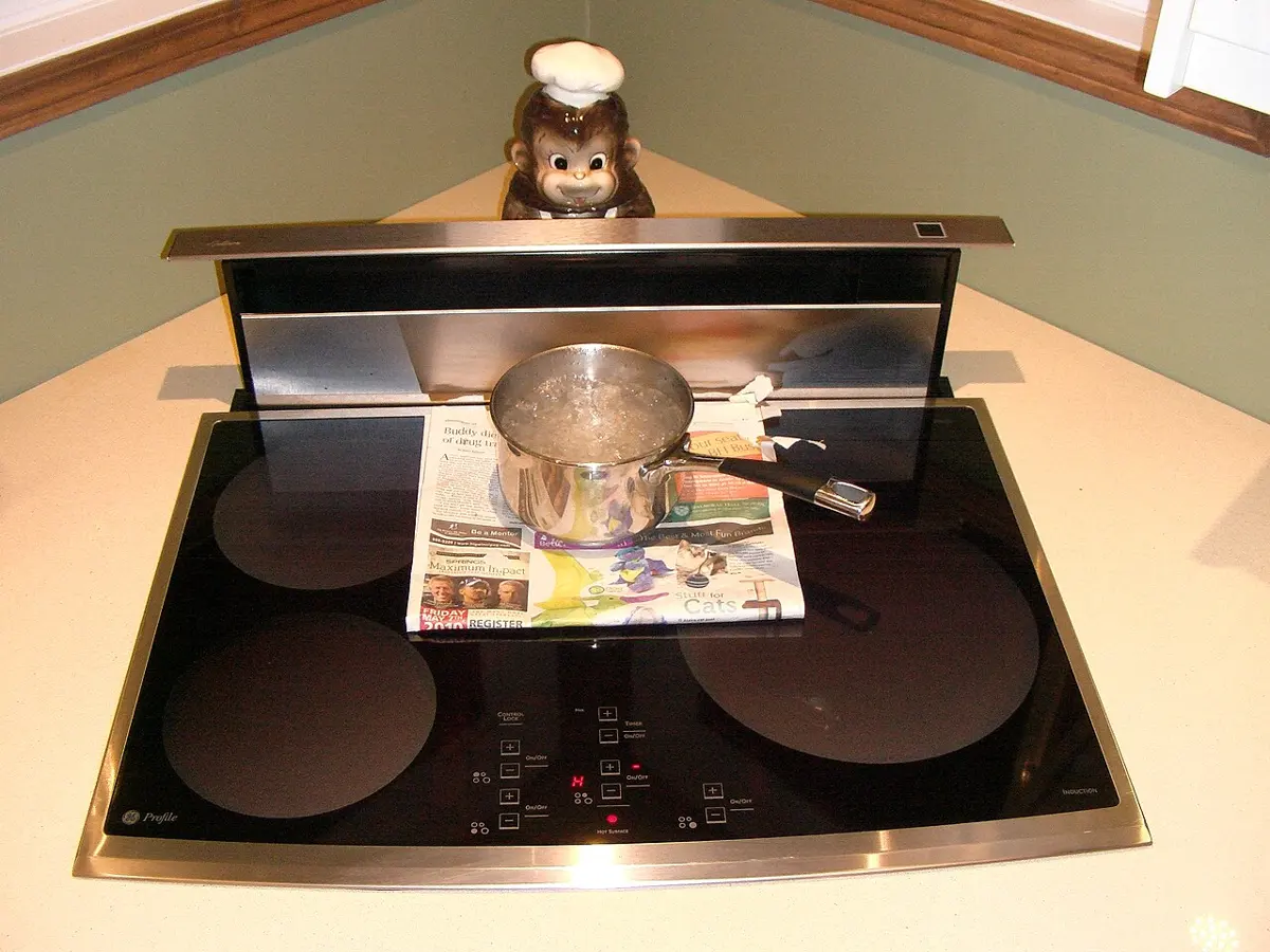
- Induction cooker: the same idea in a kitchen: a coil under the glass makes eddy currents in the steel bottom of the pan, so the pan itself gets hot.
- Induction motor: a rotating magnetic field induces eddy currents in the rotor, and the force on them drags the rotor round after the field. The rotor always turns a little slower than the field (if it kept up, the flux through it would stop changing and the currents would stop).
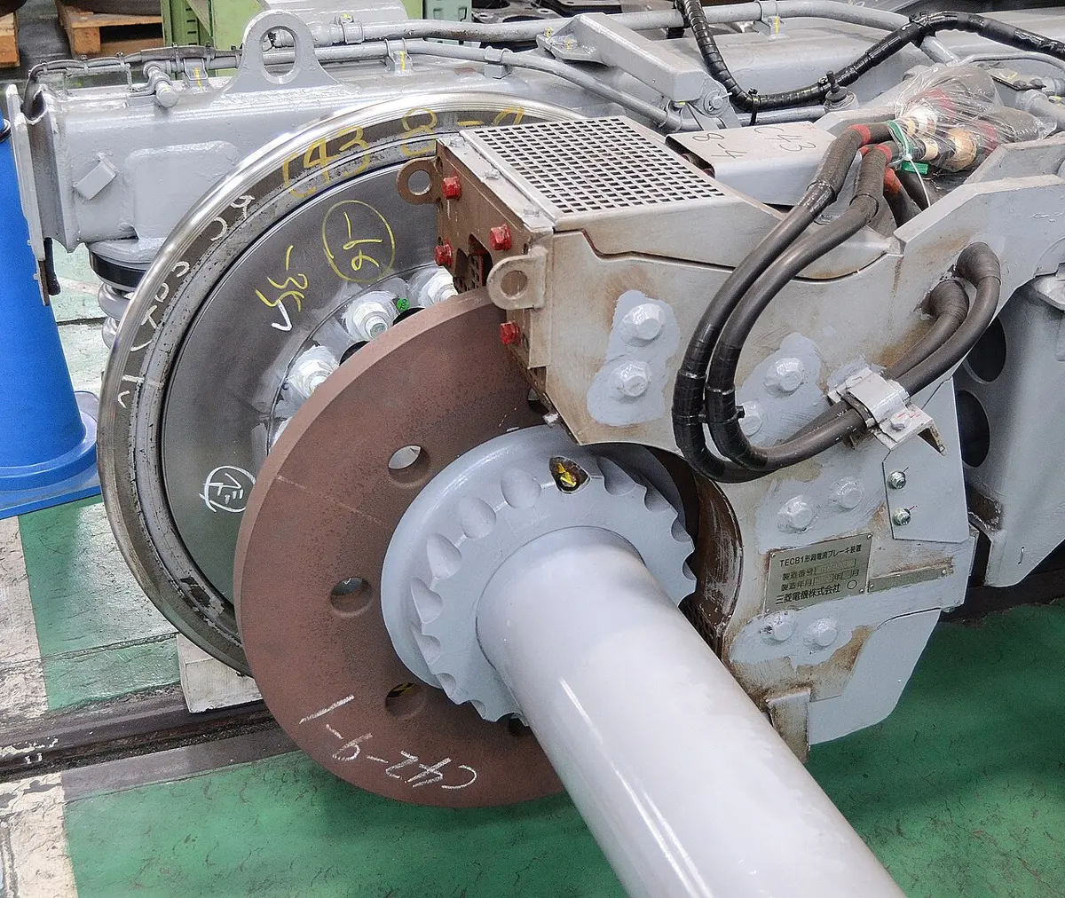
- Electromagnetic brakes: in some trains and roller-coasters, strong magnets near a metal disc or rail, which turns or moves with the wheels, induce eddy currents that brake it smoothly, with no wear.
- Diathermy (inductothermy): eddy currents induced by high-frequency fields are used to heat tissues deep inside the body, for treatment.
- Speedometer: in an old-style vehicle speedometer, a magnet turned by the wheels spins inside an aluminium cup. Eddy currents in the cup drag it round against a hairspring, by an amount that grows with the speed, moving the pointer.
- Metal detectors at airports and in mine-clearing work by sensing the eddy currents a changing field induces in buried or hidden metal.
A transformer’s core is laminated to:
Pick an answer to see why.
18.5 Self and mutual induction
Self-induction
A coil is connected to a battery E and a key K. When the key is pressed, a current starts to flow and grows. As it grows, the coil’s own magnetic field grows, so the flux through the coil’s own turns increases, and by Faraday’s law an e.m.f. is induced in the coil itself. By Lenz’s law this e.m.f. opposes the growth of the current.
When the key is released, the current falls, the coil’s field and flux decrease, and again an e.m.f. is induced, this time opposing the decrease: it tries to keep the current going (which is why you may see a spark at the key).
In both cases the e.m.f. induced in the coil opposes the change of its own current. It is called the back e.m.f.
Self-induction is the production of an induced e.m.f. in a coil because of a change in the current, and so in the magnetic flux, linked with the coil itself.
So a coil opposes any change in its current, as a heavy body opposes any change in its velocity: self-induction is the electrical inertia of a circuit.
Coefficient of self-induction
The flux linked with a coil is caused by its own current, so it is directly proportional to the current I:
The constant L is the coefficient of self-induction, or the self-inductance, of the coil. It depends on the number of turns, the area of cross-section and the permeability of the core material. For a single loop (N = 1) this is Φ = LI.
The induced e.m.f. is then
where dI/dt is the rate of change of the current in the coil. The minus sign shows that the e.m.f. opposes the change in current.
Unit of self-inductance. The SI unit is the henry (H), after the American physicist Joseph Henry, who found self-induction in 1832. From ε = L dI/dt, 1 H = 1 V s/A, and from NΦ = LI, 1 H = 1 Wb/A. The self-inductance of a coil is one henry if a current changing at 1 ampere per second induces an e.m.f. of 1 volt in it.
Test yourself 18.13. A graph of the magnetic flux linked with a coil against the current in it is drawn for two coils, A and B. Both are straight lines through the origin, A’s steeper than B’s. Which statement is correct?
Pick an answer to see why.
Self-inductance of a long solenoid
Take a long solenoid (a coil much longer than it is wide) of length l, cross-sectional area A and N turns in all, with air (strictly, a vacuum) inside, carrying a current I.
The field inside a long solenoid is uniform: , where n = N/l is the number of turns per unit length. So
The flux through each turn is
The flux linkage of all N turns is
Since NΦ = LI,
With a core of permeability μ (= μrμ₀) filling it, μ₀ becomes μ. So the self-inductance of a coil is:
- directly proportional to the permeability of the core (an iron core can raise L hundreds of times);
- directly proportional to the area of cross-section A;
- directly proportional to the square of the number of turns, L ∝ N² (doubling the turns doubles the field and doubles the turns it links);
- inversely proportional to the length l, for the same number of turns.
The inductance doesn’t depend on the current: it is fixed by the coil’s shape and core, as a resistor’s resistance is by its length, area and material. A straight wire has very little self-inductance (in exams it is taken as zero), since its field links hardly any of its own flux.
A solenoid is stretched to twice its length, keeping the same turns and area. Its self-inductance becomes:
Pick an answer to see why.
Uses of self-inductance:
- Chokes: a coil of large inductance (and small resistance) in series with a circuit opposes rapid changes in current. It limits the current in a.c. circuits, as in the ballast of an old tube light, wasting very little energy, and blocks or filters high-frequency signals.
- Smoothing: inductors store energy in their magnetic field and give it back, smoothing out ripples in the current from a power supply.
- Tuned circuits: a coil with a capacitor (an LC circuit) picks out one frequency, as when a radio or television is tuned to a station.
- Transformers: the self-inductance of the primary coil keeps the current in it small when no load is connected.
- Induction heating and sparks: the large back e.m.f. when the current in a coil is suddenly broken makes the spark of a car’s ignition coil, and the coils of induction heaters drive the eddy currents that heat the metal.
Mutual induction
Two coils, P (the primary) and S (the secondary), are placed close together. A battery and a key K are connected to P, and a galvanometer G to S.
When the key is pressed, the current in P starts to grow, and so does its magnetic flux. This growing flux induces an opposing e.m.f. in P itself (self-induction). But because S is close by, much of P’s flux passes through S too, and the growing flux through S induces an e.m.f. in S as well. By Lenz’s law, the current it drives in S makes a field that opposes the growth of P’s flux: the galvanometer kicks.
When the key is released, P’s current and flux fall, and an e.m.f. is induced in S again, but of the opposite sign: the galvanometer kicks the other way. While the current in P is steady, nothing happens in S.
Mutual induction is the production of an induced e.m.f. in a coil because of a change in the current, and so in the magnetic flux, in a neighboring coil.
Coefficient of mutual induction
The flux linked with S is caused by the current I in P, so it is directly proportional to it:
The constant M is the coefficient of mutual induction, or the mutual inductance, of the pair of coils. If I = 1 A, then NSΦS = M: the mutual inductance is numerically equal to the flux linked with one coil when a current of 1 A flows in the other. It depends on the number of turns of each coil, their sizes and shapes, the distance and angle between them, and the core (an iron core joining them makes M much larger). The same M works both ways: a current I in S links the same flux MI with P.
The e.m.f. induced in S is then
where dI/dt is the rate of change of the current in P. The minus sign shows that the e.m.f. opposes the change.
Unit: the SI unit of mutual inductance is also the henry. Two coils have a mutual inductance of 1 H if a current changing at 1 A/s in one induces an e.m.f. of 1 V in the other.
Uses of mutual induction:
- Transformers (Section 18.7) transfer electrical energy from one coil to another, stepping the voltage up or down.
- Wireless charging: a coil in the charging pad and a coil in the phone form a pair; an alternating current in the pad’s coil induces a current in the phone’s.
- Induction motors: the stator’s changing field induces the currents in the rotor.
- Signal coupling: coils pass signals from one stage of a radio circuit, or an antenna, to the next without a wire joining them.
- Sensors: inductive proximity sensors and metal detectors sense metal from the change it makes in a coil’s induced e.m.f.
18.6 Energy stored in an inductor
When a current is switched on in a coil, the back e.m.f. opposes its growth, and the source must do work to push charge against it. Once the current is steady, the back e.m.f. is zero and no more work is needed against it. The work done while the current grew is not lost: it is stored as magnetic potential energy in the coil’s magnetic field. It is the energy stored in an inductor, and it comes back out when the current falls (as the spark when the circuit is broken).
Derivation. At some instant the current is i, growing at the rate di/dt.
The back e.m.f. is (in size).
To push a charge dq = i dt against it, the source does work
The total work done while the current grows from 0 to I is
This is the energy stored:
Compare it with the kinetic energy of a moving body, . Mass resists changes in velocity; inductance resists changes in current. Inductance plays the part of inertia, and current the part of velocity. A resistor is different: it turns electrical energy into heat, for good (I²R, all the time a current flows). An inductor only stores energy for a while, in its magnetic field, and can give it back to the circuit, as a spring stores and returns mechanical energy.
The energy depends on:
- the inductance L: for a given current, a larger inductance stores more energy;
- the current I: the energy is proportional to the square of the current (double the current, four times the energy).
Where the energy is. For a long solenoid, and , so
Al is the volume inside the solenoid, where its field is. So the energy is stored in the magnetic field itself, with an energy density (energy per unit volume) of
The current in a coil is doubled. The energy stored in its magnetic field becomes:
Pick an answer to see why.
18.7 Transformer
A transformer is a device that changes an alternating voltage: a low alternating voltage at a high current into a high voltage at a low current, or the other way round.
Principle: mutual induction. A changing current, and so a changing magnetic flux, in one coil induces an e.m.f. in another coil linked with the same flux.
Construction: two separate coils of insulated copper wire, the primary P and the secondary S, wound on the same laminated soft iron core. The a.c. supply is connected to the primary, and the output is taken from the secondary. The core is made of thin strips of soft iron, coated with varnish to insulate them from one another, to reduce the energy lost to eddy currents.
Types:
- Step-up transformer: the secondary has more turns than the primary, NS > NP. It turns a low voltage at a high current into a high voltage at a low current.
- Step-down transformer: the secondary has fewer turns, NS < NP. It turns a high voltage at a low current into a low voltage at a high current.
Theory. An alternating e.m.f. EP is applied to the primary. The alternating current in it makes an alternating flux in the core. Assume the core carries all of this flux through the secondary too (no flux leaks out), so the flux Φ through each turn is the same in both coils. If it changes at the rate dΦ/dt:
The e.m.f. induced in the primary, which (for a coil of negligible resistance) balances the applied e.m.f., is
because the flux changes through each of its NP turns.The e.m.f. induced in the secondary is
Dividing (18.8) by (18.7):
The ratio NS/NP (= k) is the transformation ratio (turns ratio). For a step-up transformer it is greater than 1; for a step-down transformer, less than 1. Since the self-inductance of each coil on the same core is proportional to the square of its turns (L ∝ N²), it also equals .
Currents. In an ideal transformer there are no energy losses, so at every instant the output power equals the input power:
Putting it all together:
A step-up transformer raises the voltage by lowering the current in the same ratio, and a step-down transformer lowers the voltage by raising the current, as the conservation of energy requires. A transformer only transforms voltages: it is not a generator of electrical energy. And it works only on a.c.: a steady current makes a steady flux, which induces nothing.
Efficiency. A real transformer loses a little energy, so its output power is a little less than its input. Its efficiency is the output power as a fraction (usually a percentage) of the input power:
Large power transformers reach 98–99%: among the most efficient machines ever built.
An ideal transformer has 200 turns on its primary and 1000 on its secondary. With 230 V a.c. on the primary and a current of 0.5 A drawn from the secondary, the primary current is:
Pick an answer to see why.
Energy losses in a transformer
- Flux leakage: the coupling is never perfect, and some of the primary’s flux doesn’t pass through the secondary. It is reduced by winding the two coils one over the other, on a closed core.
- Copper loss: the resistance of the windings turns some energy into heat (I²R). It is reduced by using thick copper wire, especially for the coil carrying the larger current.
- Iron losses, in the core:
i. Hysteresis loss: the alternating current magnetizes the core one way, then the other, 50 times a second, and each cycle of magnetization wastes some energy as heat. The energy lost per unit volume in each cycle equals the area of the core’s hysteresis loop. It is reduced by using a core of soft iron (or special silicon steel), whose loop is narrow, with a small area.
ii. Eddy-current loss: eddy currents induced in the core heat it. It is reduced by laminating the core. - Humming: the alternating magnetization makes the core’s sheets vibrate a little, 100 times a second, making the transformer’s hum; a little energy goes as sound.
Hysteresis. When a ferromagnetic material is taken round a full cycle of magnetizing field H (one way, back to zero, the other way, and back), its magnetization I lags behind the field, and the graph of I against H is a closed loop. (A graph of the flux density B against H has the same shape: in iron, B = μ₀(H + I) is almost all μ₀I.) Where the loop cuts the I axis (H = 0) is the retentivity (the magnetization left behind); where it cuts the H axis (I = 0) is the coercivity (the reverse field needed to remove the magnetization).
- Soft iron has a low coercivity and a narrow loop of small area. Its permeability and susceptibility are high, so a small field magnetizes it strongly, and a small reverse field demagnetizes it, with little loss each cycle. It is used for transformer cores and electromagnets.
- Hard steel has a high coercivity and a wide loop of large area, and a lower permeability and susceptibility. It keeps its magnetism, so it is used for permanent magnets, but it would waste a lot of energy in a transformer.
Notice in the figure that soft iron’s retentivity is not small: in a closed core it can be as large as steel’s, or larger. What makes a magnet “permanent” is a high coercivity, so that knocks, heat and stray fields can’t undo it; a small reverse field, or a knock, wipes out soft iron’s magnetism.
Transformers and long-distance transmission
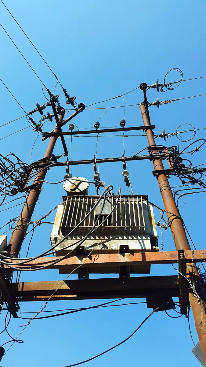
A power station may be far from the towns that use its electricity. The power lost as heat in the transmission lines, of resistance R, is I²R, so for a given power P = VI, the lower the current, the less is lost. Stepping the voltage up n times cuts the current to 1/n of its value, and the heat loss to 1/n².
So at the power station a step-up transformer raises the generator’s voltage (in Nepal, usually 11 kV) to 132 kV or 220 kV for the long lines, or 400 kV on the Dhalkebar–Muzaffarpur line to India. Near the towns, step-down transformers lower it in stages: to 33 kV or 11 kV for local lines, and finally to 230 V on the pole outside your home. High voltage is dangerous, so it is stepped down before it reaches homes, and appliances are made for 230 V; as the voltage comes down, the current in the local wires goes up.
In short, about transformers and transmission:
- A soft iron core carries the flux from the primary to the secondary, so that nearly all of it links both coils.
- Laminated cores reduce eddy currents and overheating in transformers, and the laminated armatures of motors and generators do the same for them.
- A.c. is used for transmission because transformers can change its voltage easily and with little loss.
- High voltage, low current reduces the heat lost in the lines (H = I²Rt).
Exercise
Choose the correct option
- A conducting wire 10 cm long moves at 10 m/s at right angles to a magnetic field of flux density 0.01 T. The e.m.f. induced in it is:
Pick an answer to see why.
- Lenz’s law is a statement of the law of conservation of:
Pick an answer to see why.
- Which of these circuit elements opposes a change in the current in a circuit?
Pick an answer to see why.
- A coil of N turns and area A turns with angular velocity ω in a uniform magnetic field B. The greatest e.m.f. induced in it is:
Pick an answer to see why.
- A rectangular loop of sides 8 cm and 2 cm, with a resistance of 1.6 Ω, lies in a magnetic field of 0.3 T at right angles to the loop. The field is steadily reduced at 0.02 T/s. How much power is dissipated in the loop as heat?
Pick an answer to see why.
- A current of 3 A in the primary coil is reduced to zero in 0.001 s, and the e.m.f. induced in the secondary is 15 000 V. The mutual inductance of the two coils is:
Pick an answer to see why.
- The magnetic flux linked with a coil is (in webers, with t in seconds). The magnitude of the e.m.f. induced in the coil at t = 4 s is:
Pick an answer to see why.
- A current changing at 3 A/s in one coil induces an e.m.f. of 8 mV in a nearby coil. The mutual inductance of the two coils is:
Pick an answer to see why.
- A coil of wire of radius r has 600 turns and a self-inductance of 108 mH. The self-inductance of a similar coil of 500 turns is:
Pick an answer to see why.
- What is the coefficient of mutual induction when the magnetic flux linked with one coil changes by 2 × 10⁻² Wb for a change of 0.01 A in the current in the other?
Pick an answer to see why.
Answer the following
- a.State Faraday’s laws of electromagnetic induction.
- b.A coil has 5000 turns. What e.m.f. is induced in it when the magnetic flux through it changes by 8 × 10⁻⁴ Wb in 0.1 s?
- c.A light aluminium ring hangs from a long thread, with a bar magnet near it along its axis. When the magnet is moved away from the ring, the ring follows the magnet. Why? What would happen if the magnet were moved towards the ring?
Answer
Lenz’s law gives the direction of an induced e.m.f.
- a.State Lenz’s law.
- b.A straight conductor carries an increasing current from A to B, with a circular loop above it in the same plane. Find the direction of the current induced in the loop, and give your reasoning.
- c.A rectangular metal frame PQRS, 4.0 cm wide (QR) and 7.0 cm tall (PQ), stands in a vertical plane in a uniform horizontal magnetic field of 4.5 × 10⁻³ T, directed along QR. A current of 2.5 A flows round it, up RS, along RQ and down QP. If the frame turns with a steady angular velocity ω about a vertical axis through its middle, obtain an expression for the e.m.f. induced in it.
- d.Calculate the force on the side PQ.
- e.Why does the side QR feel no force?
Hint
Answer
Lenz’s law gives the direction of an induced e.m.f.
- a.Explain how Lenz’s law agrees with the conservation of energy.
- b.A straight vertical conductor carries an increasing current from P (below) to Q (above), with a circular loop to its right in the same plane. Find the direction of the current induced in the loop, and give your reasoning.
- c.What is called the electrical inertia of a circuit? Find its expression for a solenoid.
- d.What is the electrical inertia of a straight conductor?
- e.A wheel with metal spokes 1.2 m long turns in a magnetic field of flux density 5 × 10⁻⁵ T at right angles to its plane. An e.m.f. of 10⁻² V is induced between the rim and the axle. Find the rate of rotation of the wheel.
Answer
- a.State Faraday’s quantitative law of electromagnetic induction.
- b.State and explain Lenz’s law.
- c.A solenoid S is wound on a soft iron core. A coil C of 120 turns is wound on one end of the core; its area of cross-section is 1.5 cm². A Hall probe is close to the other end of the core. When there is a constant current in S, the flux density in the core is 0.19 T, and the voltmeter connected to the Hall probe reads 0.20 V. The current in S is now reversed in 0.13 s, at a constant rate.
- i.Calculate the reading of the voltmeter connected to coil C while the current is changing.
- ii.Copy and complete the table of voltmeter readings before, during (at the instant the current is zero) and after the reversal.
| before the current changes | during the change, when the current is zero | after the current changes | |
|---|---|---|---|
| voltmeter on coil C (V) | … | … | … |
| voltmeter on the Hall probe (V) | 0.20 | … | … |
Hint
Answer
A solenoid is connected in series with a battery and a switch. A small coil, connected to a sensitive ammeter, is placed near one end of the solenoid, on its axis. As the current in the solenoid is switched on, there is a changing magnetic field inside the solenoid.
- a.i. State Faraday’s qualitative law of electromagnetic induction.
- ii.Explain how to find the direction of the magnetic field inside the solenoid (arrow P on the axis).
- b.As the current in the solenoid is switched on, a current is induced in the small coil, and it gives rise to a magnetic field in the small coil.
- i.Lenz’s law governs the direction of the induced current. Which fundamental principle of physics is it based on?
- ii.Use Lenz’s law to state and explain the direction of the magnetic field due to the induced current in the small coil.
- c.The small coil has an area of cross-section 7.0 × 10⁻⁴ m² and 75 turns. A constant current in the solenoid makes a uniform field of flux density 1.4 mT throughout the small coil. The direction of the current in the solenoid is reversed in 0.12 s. Calculate the average e.m.f. induced in the small coil.
Answer
- a.An ideal transformer has a primary coil of 2700 turns and a secondary coil of 450 turns on a soft iron core, with a load resistor connected to the secondary. Explain why, when there is an alternating current in the primary coil, there is a current in the load resistor.
- b.A step-down transformer is used on a 220 V line to supply a current of 0.5 A to a 15 W bulb. If the secondary has 20 turns, find the number of turns in the primary and the current in the primary.
Answer
A straight electrical conductor is placed between the poles of a U-shaped magnet (Figure 18.31). The field in the gap is horizontal, from one pole to the other, and the conductor lies across it. The ends of the conductor are connected to a voltmeter.
- a.Name a material an electrical conductor can be made from.
- b.i. The voltmeter measures the e.m.f. across the conductor. State the unit of e.m.f.
- ii.State what, if anything, the meter shows when the conductor is moved: horizontally, from side to side, between the poles (towards one pole and then the other); vertically, up and down, between the poles.
- c.State two factors that affect the size of the e.m.f. across the conductor.
Answer
- a.A teacher hangs a bar magnet, north pole down, from a spring above a coil connected to a center-zero millivoltmeter. The teacher pulls the magnet down until its lower end is inside the coil, and releases it. The magnet moves up and down again and again, its end entering and leaving the coil. Describe and explain the readings on the millivoltmeter.
- b.Electricity from a power station at 22 000 V is sent along a 132 000 V line to homes that use 240 V. Name the device used at X (between the station and the line) and at Y (between the line and the homes).
Answer
A small rectangular coil ABCD has 140 turns of wire. Its sides AB and BC are 4.5 cm and 2.8 cm long. The coil is held between the poles of a large magnet so that it can turn about an axis through its center, parallel to AB. The magnet makes a uniform field of flux density B between its poles. When the current in the coil is 170 mA, the greatest torque on the coil is 2.1 × 10⁻³ N m.
- a.For the coil in the position of greatest torque, is the plane of the coil parallel to the field, or at right angles to it?
- b.With the coil in that position, calculate the magnitude of the force on i. side AB, ii. side BC.
- c.Use your answer to b.i. to show that B is 70 mT.
- d.i. State Faraday’s law of electromagnetic induction.
- ii.The current in the coil is switched off, and the coil is left as in Figure 18.34, its plane parallel to the field. It is then turned through 90° in 0.14 s. Calculate the average e.m.f. induced in the coil.
Hint
Answer
A simple a.c. generator has a coil that turns between the poles of a magnet, its ends joined to two slip rings. When the coil turns, an e.m.f. is induced in it.
- a.Explain why an e.m.f. is induced.
- b.State the purpose of the slip rings.
- c.The direction of the current in the coil can be found from Lenz’s law. State and explain Lenz’s law.
- d.The induced e.m.f. can be increased by turning the coil faster. State two other ways in which it can be increased.
Answer
A farmer connects a house to the mains. The house is a long way from the nearest 230 V supply, and is joined to it by long cables.
- a.The farmer uses 230 V lamps in the house, but they do not light up at full brightness. Explain why the lamps are dim.
- b.The farmer then adds a transformer A next to the supply and a transformer B next to the house. Now the lamps light up at full brightness. Explain why.
- c.The 230 V supply provides 690 W of power to transformer A.
- i.Calculate the current supplied to the transformer.
- ii.Calculate the energy supplied to the transformer in 10 minutes, in joules.
Answer
Printable PDFs
- The unit as a book (A5) 39 pages Answers as an A4 booklet, 10 sheets
- Study notes 3 pages
- Worksheet 4 pages Answer key
- Harder practice questions 2 pages Answer key
Quiz yourself: Electricity and Magnetism, Grades 5–12 →
Practice every question in the book, and keep track of the ones you miss →
A companion to your textbook, not a replacement for it: study from the book your school uses, and where the two differ, follow your teacher. Found a mistake? Please tell us.