
Hold a compass under the cable of an electric kettle in Bhaktapur and switch the kettle on. Nothing happens: the cable carries two currents, in and out, side by side, and their magnetic effects cancel. Pull the two wires apart and lay one alone over the compass, and the needle swings the moment the current flows. That swing, first seen in 1820, is the start of this unit. Every motor, loudspeaker, hard disk, MRI scanner and electricity meter works because a current makes a magnetic field, and a magnetic field pushes on a current.
In this unit you will meet the magnetic field and its flux, find the force on a moving charge and on a wire, see why a coil turns in a field (and how that turning measures current), use the Hall effect to measure a field, and work out the field of a wire, a loop, a solenoid and a toroid, by the Biot–Savart law and by Ampère’s law. It ends with two wires pulling on each other: the force that defined the ampere.
16.1 Magnetic field and magnetic flux
How can a current, a flow of charge, turn a magnet that it never touches?
Oersted’s discovery
Oersted’s experiment showed the link between electricity and magnetism. When a current flows through a wire, it makes a magnetic field around the wire, and a compass needle placed near it is turned. Oersted found that:
- the needle turns only while the current flows;
- a larger current turns it more;
- reversing the current turns the needle the other way.
The experiment proved that electricity can make magnetism, and laid the ground for electromagnetism: the electric motor, the generator and the transformer all grew from it.
What Oersted’s discovery did not explain
Oersted’s discovery was a first step. It left a great deal for others to find:
- It showed that a current makes a magnetic field, but not how strong the field is or how it changes with distance from the wire (the Biot–Savart law, Section 16.9).
- It didn’t show the full shape and direction of the field round the wire: circles round it, as Ampère and others showed (Section 16.2).
- Oersted used a steady current, so his experiment couldn’t show what happens when a current changes: that a changing magnetic field makes an e.m.f. (Faraday, 1831, the next unit).
- It didn’t show that electric and magnetic fields can travel together as waves: Maxwell showed that in the 1860s, and found that light is such a wave.
- It didn’t explain how a magnetic field pushes on moving charges (Section 16.3), which is what makes motors work.
Magnetic lines of force
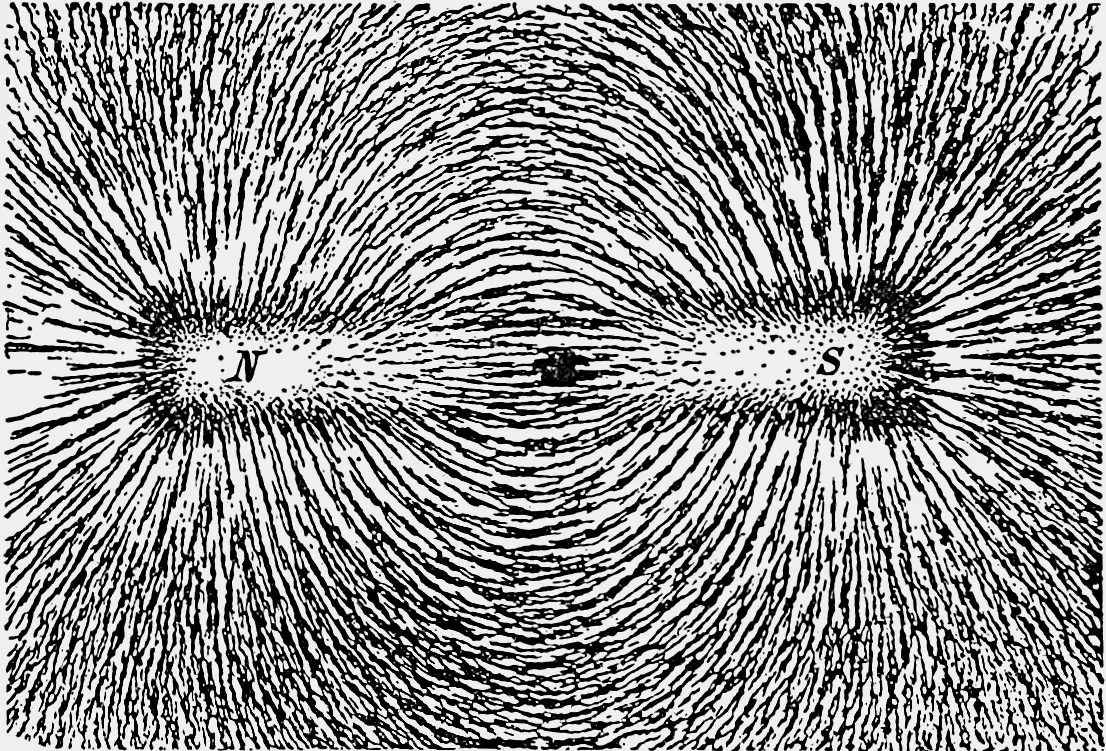
A magnetic line of force (a magnetic field line) is an imaginary line drawn so that the tangent to it at any point gives the direction of the magnetic field there: the way a small compass needle placed there would point. An older definition says the same thing: it is the path along which a free, isolated north pole would move. (No isolated north pole has ever been found, but the idea gives the field’s direction.)
The lines can be drawn with a compass. With the paper on the bar magnet, place a small compass near the N pole, mark the two ends of its needle with dots, move the compass on so that its tail is at the last dot, mark again, and so on: joining the dots gives one line.
The properties of magnetic lines of force:
- Outside a magnet, they come out of the north pole and go into the south pole.
- Inside the magnet, they run from the south pole to the north pole, so each line is a closed loop (magnetic field lines have no beginning or end).
- They never cross each other. The tangent at a point gives the field’s direction there; if two lines crossed, the field would have two directions at one point, which is impossible.
- Where the lines are closer together, the field is stronger: the field’s strength is in proportion to the number of lines crossing a unit area at right angles. So the lines are crowded near the poles and spread out farther away.
- Lines of force running side by side in the same direction push each other apart sideways, and each line acts as if it were stretched, trying to shorten. This is a useful way of picturing forces: two N poles facing each other push apart, and an N and an S pull together.
Why can two magnetic lines of force never cross?
Pick an answer to see why.
Magnetic flux
To talk about “how much field passes through a coil”, we need a name for it. The magnetic flux through a plane surface is the product of the area and the component of the magnetic field at right angles to it:
when the field is normal (at right angles) to the surface of area . If the field makes an angle θ with the normal to the surface,
Only the field’s component along the normal, , passes through the surface. In vector form, , where is a vector of size A along the normal. Flux is a scalar.
You can picture flux as the number of lines of force passing through the surface: tilt the sheet, and fewer lines cross it.
Units of magnetic flux
In SI, the unit of magnetic flux is the weber (Wb). A uniform field of 1 tesla at right angles to an area of 1 m² gives a flux of 1 weber. From , the field is a flux per unit area, so
and the field is also called the magnetic flux density. In terms of other units, 1 Wb = 1 T m² = 1 N m/A (= 1 V s, as the next unit shows).
In the older CGS system, flux is measured in maxwells (Mx) and flux density in gauss (G), with 1 G = 1 Mx/cm². Since 1 T = 1 Wb/m² and 1 m² = 10⁴ cm²,
Flux linked with a coil
A coil of N turns, each of area A, placed at right angles to a uniform field B, has the flux BA through each turn. The total, called the flux linkage, is
and if the field makes an angle θ with the normal to the coil’s plane,
Dimensions of magnetic flux
From the force on a moving charge (Section 16.3), , so (since q = It). Then
and the flux density B has dimensions .
Test yourself 16.1. A magnetic field is (in some unit). The magnetic flux through a surface of area 20 units lying in the y–z plane is:
Pick an answer to see why.
A coil of 50 turns, each of area 40 cm², is in a uniform field of 0.2 T. Its plane makes an angle of 30° with the field. The flux linkage is:
Pick an answer to see why.
Magnetic flux density
The magnetic flux density at a point is the magnetic flux per unit area through a small area held at right angles to the field there:
It tells how concentrated the lines of force are. It is a vector, in the direction of the field, and it is what is usually called simply “the magnetic field”. Its SI unit is the tesla (T); in CGS it is the gauss (1 T = 10⁴ G). Section 16.3 gives it a second, equivalent definition, by the force it exerts on a moving charge.
A second quantity, the magnetic field intensity (magnetizing field) , describes the field made by currents alone, whatever material is present. In a vacuum (or air) . Its SI unit is the ampere per meter (A/m), and its CGS unit the oersted (Oe). Unit 17 uses it.
Neutral points
A compass on a table feels two fields at once: the Earth’s, whose horizontal component (the part along the table) points to magnetic north, and that of any magnet nearby. They add as vectors. Where they are equal and opposite, the resultant field is zero.
A neutral point is a point where the field of a magnet is equal and opposite to the horizontal component of the Earth’s field, so that the resultant field there is zero. A compass placed at a neutral point doesn’t point in any particular direction: it stays wherever it is left.
Where the neutral points are depends on how the magnet is placed in the magnetic meridian (the north–south line):
- N pole pointing north: to either side of the magnet’s middle, the magnet’s own field runs from its N end back to its S end, southward, against the Earth’s field. The two neutral points lie east and west, on the magnet’s equatorial line (the line through its middle at right angles to it).
- N pole pointing south: beyond the N end (south of the magnet) the magnet’s field points away from the N pole, southward; beyond the S end (north of the magnet) it points into the S pole, southward again. On both sides it runs against the Earth’s northward field, so the two neutral points lie on the axial line, beyond the two ends.
A bar magnet lies on a table with its N pole pointing geographic south. A compass is placed at one of its neutral points. The compass:
Pick an answer to see why.
16.2 Direction of the magnetic field round a current
What shape does the field of a straight wire have, and which way does it go round?
Three rules give the field’s direction.
i. The right-hand thumb rule (for a straight conductor). Grasp the conductor in your right hand with the thumb pointing in the direction of the current. Your fingers then curl round the wire in the direction of the magnetic lines of force.
ii. Maxwell’s corkscrew rule (for a straight conductor). Imagine a right-handed corkscrew (or an ordinary screw) being turned so that it moves forward along the conductor in the direction of the current. The direction in which its handle turns is the direction of the magnetic lines of force. A screw goes in when turned clockwise (seen from behind): so a current going away from you has a field going clockwise round it.
iii. The right-hand grip rule (for a circular coil or a solenoid). Curl the fingers of your right hand round the coil in the direction of the current in its turns. Your thumb then points in the direction of the magnetic field along the coil’s axis: towards the coil’s N pole.
A long straight wire carries a current vertically downward through a horizontal card. Seen from above, the field lines round it on the card go:
Pick an answer to see why.
16.3 Force on a moving charge: the Lorentz magnetic force
A magnetic field pushes on a current. But a current is only charges on the move. Does the field push on each moving charge?
It does. Take a charge +q moving with velocity in a uniform magnetic field . Let the field point along the z-axis, and let the charge move in the y–z plane, its velocity at an angle θ to the field. Experiments show that the charge feels a force along the x-axis: at right angles to both the velocity and the field. Its size is:
- i.directly proportional to the charge: … (16.5)
- ii.directly proportional to the component of the velocity at right angles to the field: … (16.6)
- iii.directly proportional to the field: … (16.7)
Combining the three, , or . In SI the unit of B is chosen so that k = 1:
In vector form, giving its direction as well,
This is the Lorentz magnetic force. It is always at right angles to both and . For a negative charge (an electron) the force is the other way.
Equation (16.8) also defines the tesla: a field of 1 T exerts a force of 1 N on a charge of 1 C moving at 1 m/s at right angles to it. So 1 T = 1 N/(C m/s) = 1 N/(A m).
Special cases:
- i. Moving at right angles to the field (θ = 90°): , the largest force. As Section 16.4 shows, the charge then moves in a circle.
- ii. Moving along the field (parallel or antiparallel, θ = 0° or 180°): . The field has no effect on it.
- iii. A charge at rest (v = 0): . A magnetic field exerts no force on a charge at rest. (A neutral particle, with q = 0, feels no magnetic force either.)
An electron and a proton move side by side with the same velocity, at right angles to a uniform magnetic field. The magnetic forces on them are:
Pick an answer to see why.
Fleming’s left-hand rule
The direction of the force on a positive charge, or on a current, is given by Fleming’s left-hand rule. Stretch the thumb, forefinger and middle finger of your left hand so that they are all at right angles to each other. Point the forefinger along the field (B) and the middle finger along the motion of the positive charge, the current (I or v). The thumb then points along the force (F).
A way to remember it: First finger, Field; seCond finger, Current; thuMb, Motion.
16.4 Motion of a charged particle in a uniform magnetic field
If a magnetic field can never speed a charge up or slow it down, what can it do?
It can only turn it. What path the charge takes depends on the angle between its velocity and the field.
Moving at right angles to the field: a circle
Let a particle of mass m and charge q move with speed v at right angles to a uniform field B. The force is always at right angles to its velocity, and the same size everywhere: exactly what is needed for uniform circular motion. The magnetic force provides the centripetal force:
A faster particle, or a heavier one, moves in a bigger circle; a stronger field bends it more tightly. The time for one round, the period, is
The speed has canceled out: in a given field, a particle takes the same time for each circle whatever its speed. A faster one goes round a bigger circle in the same time. This frequency is the cyclotron frequency: the cyclotron, a particle accelerator, gives particles a push at that steady beat, and they spiral outward as they speed up.
At an angle to the field: a helix
If the velocity makes an angle θ with the field, split it into two parts:
- along the field, which feels no force and stays the same;
- at right angles to it, which is turned round in a circle of radius , in the same period .
Together they make a helix (a spiral like a spring) round the field lines. In each period it moves along the field a distance called the pitch:
Crossed electric and magnetic fields: the velocity selector
Put an electric field E and a magnetic field B at right angles to each other and to a beam of charged particles, arranged so that the two forces on a particle are opposite. The electric force qE is the same for every particle; the magnetic force qvB depends on its speed. Only particles for which
pass straight through. Slower ones are pushed one way, faster ones the other. The condition doesn’t depend on the charge or the mass: this velocity selector picks out particles of one speed, whatever they are. J. J. Thomson used it in 1897 to measure the electron’s charge-to-mass ratio, the start of Unit 19.
16.5 Force on a current-carrying conductor in a magnetic field
The current in a wire is a stream of free electrons drifting along it. In a magnetic field, each feels a Lorentz force; the wire passes the push on to itself (Test yourself 16.3). Adding up the forces on all the electrons gives the force on the wire.
Take a straight conductor of length l and cross-sectional area A, carrying a current I, at an angle θ to a uniform field B. Let it have n free electrons per unit volume, each of charge e, drifting with speed .
Step 1. Each electron feels a force .
Step 2. The wire holds free electrons (its volume times n), so the total force is
Step 3. But the current is (Grade 11, Unit 23). So
In vector form, , where has the wire’s length and points along the current. The force is at right angles to both the wire and the field, as Fleming’s left-hand rule gives. This holds when the field is uniform along the whole length of the wire.
Special cases:
- Case I. The wire along the field (θ = 0° or 180°): sin θ = 0, so F = 0. A wire parallel to the field feels no force.
- Case II. The wire at right angles to the field (θ = 90°): sin θ = 1, so F = BIl, the largest force.
A straight wire carrying a current lies along the lines of a uniform magnetic field. The force on it:
Pick an answer to see why.
16.6 Force and torque on a rectangular coil in a uniform magnetic field
Why does a coil in a magnetic field turn, when the forces on it add up to zero?
When a current passes round a rectangular coil in a uniform magnetic field, the forces on its sides produce a torque that turns the coil until its plane is at right angles to the field. This turning is how every electric motor and every moving-coil meter works.
Take a rectangular coil PQRS of N turns, carrying a current I, in a uniform field B. Let its sides PQ and RS, of length l, be at right angles to the field, and its sides QR and SP have length b (the breadth). The coil can turn about an axis through its middle, parallel to PQ. Let the plane of the coil make an angle α with the field; then the normal to the coil makes an angle θ = 90° − α with it.
Step 1. The forces. Sides PQ and RS are at right angles to the field, so each feels a force (16.11) per turn. The currents in them are opposite, so the forces are equal and opposite, at right angles to the field.
Step 2. The other two sides. The forces on QR and SP are also equal and opposite, but they act along the same line (the axis of turning), so they cancel completely and give no torque.
Step 3. The torque. The forces on PQ and RS act along parallel lines a perpendicular distance apart, so they form a couple:
where is the coil’s area. For N turns,
Step 4. Vector form. Define the coil’s magnetic dipole moment , of size NIA, along the normal to the coil (the way the right-hand grip rule gives from the current). Then
The unit of magnetic moment is the ampere meter squared (A m²). This is the same law as for a bar magnet in a field (Unit 17): a current loop acts as a magnet whose moment is NIA.
Special cases:
- i.The coil’s plane along the field (α = 0°, θ = 90°): , the largest torque.
- ii.The coil’s plane at right angles to the field (α = 90°, θ = 0°): . The coil has turned as far as the field can turn it: its moment points along the field.
The energy of a coil, or a magnet, in a field
Turning a magnetic moment M against the field takes work. Turning it from angle θ₁ to θ₂ with the field, the torque MB sin θ does
so its potential energy is : least when the moment is along the field (θ = 0, the stable position), greatest when it points against it (θ = 180°, an unstable balance). Turning it right round, from 0° to 180°, takes .
16.7 Moving-coil galvanometer
A galvanometer is an instrument for detecting and measuring very small currents. The ammeters and voltmeters with a needle in a school lab are galvanometers inside, with resistors added (Grade 11, Unit 23).
Principle. A current-carrying coil in a magnetic field feels a torque (Section 16.6). In the galvanometer that torque is balanced by a spring, and the angle the coil turns through measures the current.
Construction. A rectangular coil of N turns of fine insulated copper wire, of length l and breadth b, is wound on a light non-magnetic frame (brass or aluminium). In the suspended-coil type, used for the most sensitive work, it hangs by a fine phosphor-bronze strip from a torsion head at the top, which can be turned to set the zero, and its lower end is joined to a loose hairspring of phosphor bronze. The current goes in and out through the suspension and the spring. The coil hangs between the concave pole pieces of a strong permanent magnet, round a fixed soft-iron cylinder, the core, so that the field in the gap is radial: it points along the radii of the core, towards its axis or away from it. A light mirror on the suspension (or a pointer) shows the deflection on a scale. In the pivoted type, used in lab meters, the coil turns on jewel bearings between two hairsprings and carries a pointer.
Working. With a current I in the coil, the forces on its two vertical sides form a couple. In a radial field, the field is always along the plane of the coil, whatever its deflection (α = 0 always), so the deflecting torque is always the largest value:
As the coil turns through an angle θ, the suspension (or the hairspring) is twisted and gives a restoring torque in proportion to the twist:
where k is the torsion constant of the suspension or spring (the torque per radian of twist). The coil comes to rest where the two torques balance:
where is the galvanometer constant. So I ∝ θ: the deflection is in direct proportion to the current, and the scale can be marked evenly. This is the theory of the moving-coil galvanometer. Without the radial field, the torque would be NBIA cos α and fall off as the coil turned, and the scale would be crowded at one end.
Current sensitivity
The current sensitivity of a galvanometer is the deflection per unit current:
A galvanometer is sensitive if a small current gives a large deflection. So it is more sensitive if:
- i.the number of turns N is large;
- ii.the magnetic field B is strong;
- iii.the area of the coil A is large;
- iv.the torsion constant k is small (a fine, soft suspension).
Voltage sensitivity
The voltage sensitivity is the deflection per unit potential difference across the galvanometer. If its coil has resistance R, then V = IR, and
It is higher for large N, B and A, small k, and small resistance R.
16.8 Hall effect
If the field pushes the moving electrons in a wire sideways, shouldn’t one side of the wire become charged?
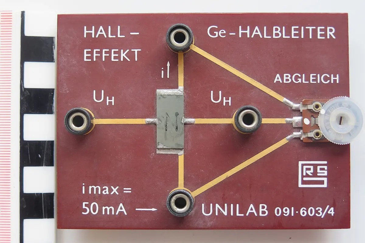
It does, very slightly. In 1879 Edwin Hall, a student at Johns Hopkins University in the United States, passed a current along a thin strip of gold leaf in a strong magnetic field and found a small voltage across the strip, at right angles to the current. When a magnetic field is applied at right angles to a current-carrying conductor, a voltage is developed across the conductor in the direction at right angles to both the current and the field. This is the Hall effect, and the voltage is the Hall voltage, .
Take a slab of conductor of width d and thickness t, so its cross-section is A = dt. A current I flows through it from left to right, along the +x-axis, so its free electrons drift from right to left with speed . A uniform field B is applied along the z-axis, at right angles to the slab’s broad face.
Step 1. Each electron feels the Lorentz force , which (for a negative charge, Fleming’s rule reversed) is vertically downward. Electrons collect on the lower face, making it negative and leaving the upper face positive.
Step 2. The charges on the two faces set up an electric field E across the slab, pointing down, and a potential difference between the faces:
This field pushes each electron upward with a force .
Step 3. Electrons go on collecting until the two forces balance, which happens almost at once. Then
Step 4. The current is , where n is the number of free electrons per unit volume, so
Step 5. Putting (16.18) into (16.17):
where t is the thickness of the slab along the field. The Hall voltage is larger for a thinner slab and for a material with fewer charge carriers per unit volume (smaller n), and it is in direct proportion to B.
Measuring a magnetic field with a Hall probe
A Hall probe measures magnetic flux density by the Hall effect. It is a thin slice of semiconductor at the flat end of a rod, with a steady current through it and leads to a voltmeter across it. Rearranging ,
For a given probe and current, n, e, t and I are fixed, so B is in direct proportion to , and the meter can be marked in teslas. For an accurate reading, the flat face must be held at right angles to the field lines: the reading is largest then, smaller when the probe is tilted, and zero when its face is along the field. A good Hall probe can detect even the Earth’s field.
16.9 Biot–Savart law
Oersted’s needle showed that a current makes a field. How strong is that field, at a given place?
In 1820, a few months after Oersted’s discovery, the French physicists Jean-Baptiste Biot and Félix Savart measured the field of a current, and Pierre-Simon Laplace put their results into a law for a small piece of the current. It is called the Biot–Savart law (or Laplace’s law). With it, the field of any shape of wire can be worked out by adding up its pieces.
Take a conductor XY carrying a current I, a small element AB of it of length dl, and a point P at a distance r from the element’s center C. Let θ be the angle between the element and the line CP. The field dB at P due to this element is:
- i.directly proportional to the current:
- ii.directly proportional to the element’s length:
- iii.directly proportional to the sine of the angle θ:
- iv.inversely proportional to the square of the distance:
Combining these, , or , where the constant k depends on the units. In SI, :
Here is the permeability of free space, H/m (henry per meter, the same as Wb/(A m) or N/A²); so H/m. (In the old CGS electromagnetic units, k = 1.)
Direction of dB. It is at right angles to both the element and the line CP, given by the right-hand thumb rule. In the figure, it points into the page at P. In vector form, .
Note two things. A point on the line of the element itself (θ = 0° or 180°) gets no field from it. And the law has the same inverse-square form as Coulomb’s law for the electric field of a charge.
A short element of a current-carrying wire makes a field dB at a point 2 cm away, at right angles to the element. At a point 4 cm away, at 30° to the element (on the other side), the field from the same element is:
Pick an answer to see why.
Applications of the Biot–Savart law
i. The field at the center of a circular coil
Take a circular loop of radius r, center O, carrying a current I. Every element dl of the loop is at the same distance r from O, and the line from it to O is at right angles to it (θ = 90°, sin θ = 1). So each element gives
and, by the right-hand thumb rule, all the dB at O point the same way, along the coil’s axis. Adding them up, , the loop’s circumference:
For a coil of N turns, close together,
Direction: along the coil’s axis, by the right-hand grip rule. Seen from one side, a current going anticlockwise gives a field coming out towards you (that face is a north pole); clockwise gives a field going away from you (a south pole).
For an arc that is only a fraction of a circle, the elements add up in the same way, but there are fewer of them: an arc that subtends an angle α (in radians) at its center gives .
ii. The field on the axis of a circular coil
Take a circular coil of radius a, center O, carrying a current I, and a point P on its axis at a distance x from O.
Step 1. Take a small element of length dl at the top of the coil, a distance from P. The line from it to P is at right angles to it (θ = 90°), so
at right angles to the line from the element to P.
Step 2. Split dB into two parts: along the axis and at right angles to it, where φ is the angle between the line from the element to P and the axis, so that .
Step 3. The element diametrically opposite gives a field of the same size whose part at right angles to the axis points the other way. Taken in pairs round the coil, the parts at right angles to the axis cancel, and only the parts along the axis add up.
Step 4. Adding the parts along the axis, with :
For N turns,
Check: at the center, x = 0, and , as before.
Far away, where x ≫ a, , and
Far from the coil the field falls as 1/x³, just like the field on the axis of a small bar magnet: a current loop is a magnetic dipole.
The field is along the axis only on the axis. At points off the axis, the field is not zero: it has parts both along and across the axis, and the lines of force loop round each side of the wire, like a bar magnet’s. (Working it out off the axis takes harder mathematics.)
Graph. B against x is bell-shaped, the same on both sides of the coil: largest at the center, falling off on both sides, never quite reaching zero.
Direction: along the axis, by the right-hand grip rule: curl the fingers of your right hand round the coil along the current, and the thumb gives the field.
iii. The field of a long solenoid
A long coil of closely packed turns is a solenoid. Its field is like a bar magnet’s: one end acts as a north pole and the other as a south pole. Inside, well away from the ends, the field is strong, uniform and along the axis. Outside, the field is very weak compared with that inside, and for a long solenoid it can be taken as zero.
Adding up the fields of all its turns by the Biot–Savart law gives, inside a long solenoid,
where n is the number of turns per unit length, n = N/l. (Section 16.10 shows the same result more simply, by Ampère’s law.) B is in direct proportion to n and to I, and does not depend on the solenoid’s radius. At either end of a long solenoid, on the axis, the field is half that inside, : the end of a long solenoid has turns on only one side of it. If the solenoid is wound on a core of relative permeability , the field is times larger, (Unit 17).
Graph. Along the axis, the field is strong and uniform over most of the solenoid’s length, falls to half near each end, and dies away outside.
Direction: along the axis, by the right-hand grip rule.
iv. The field of a straight current-carrying conductor
Take a straight conductor carrying a current I, and a point P at a perpendicular distance a from it; let O be the foot of the perpendicular.
Step 1. An element dl at a distance l from O is a distance r from P, where . Let the line from the element to P make an angle φ with PO; then and , and the angle θ between the element and that line has .
Step 2. By the Biot–Savart law,
Every element’s field at P points the same way (into the page, for the current in the figure), so they add.
Step 3. As l changes, , and
Step 4. Adding (integrating) from the angle φ₁ on one side of PO to φ₂ on the other:
Step 5. For an infinitely long wire, φ₁ = φ₂ = 90°, and
The field round a long straight wire is in inverse proportion to the distance from it. (For a wire that ends at the foot O and runs to infinity on one side, φ₁ = 0 and φ₂ = 90°, and B is half this, .)
Graph. B against the distance from the wire is a falling curve, : strongest close to the wire, weaker farther away, halving each time the distance doubles.
Direction: circles round the wire, by the right-hand thumb rule.
16.10 Ampère’s circuital law
Is there a quicker way to find the field when a current is arranged very symmetrically?
There is. Ampère’s circuital law is an alternative to the Biot–Savart law, and it is far quicker in cases with enough symmetry. It states:
The line integral of the magnetic field round any closed path equals μ₀ times the net current passing through the area bounded by the path:
Here the path is split into small steps , and the products (the field’s part along each step, times the step) are added all the way round. The result holds whatever the size and shape of the path, and it holds for steady currents. (Maxwell later added a term for changing electric fields, which led him to light as an electromagnetic wave.)
The skill in using it is to choose a path along which B is the same size everywhere and either along the path or at right angles to it. Then the integral is just B times a length.
i. A long straight conductor
The lines of force round a long straight wire are circles centered on it. Choose as the path a circle of radius r round the wire. By symmetry, B has the same size everywhere on it and points along it, so
the same result as the Biot–Savart law gave, in two lines.
ii. A long solenoid
Take a long solenoid with n turns per unit length carrying a current I. Choose a rectangular path abcd, with ab (of length l) inside the solenoid, parallel to the axis, and cd outside.
- Along ab, inside, the field is uniform and along the path: .
- Along bc and da, the path is at right angles to the field inside, and outside the field is zero: these give 0.
- Along cd, outside, the field is (almost) zero: 0.
So . The path encloses N = nl turns, each carrying I, so the current through it is NI = nlI. By Ampère’s law,
iii. A toroid
A toroid is a solenoid bent round into a ring, like a doughnut wound with wire: an endless solenoid. Its lines of force are circles inside the windings, centered on the toroid’s center; there are no ends for the field to leak out of.
Take a toroid of N turns carrying a current I, and choose as the path a circle of radius r inside the windings, centered on the toroid’s center. By symmetry, B is the same size all round it and along it:
The circle is threaded by all N turns, each carrying I, so the current enclosed is NI:
Since , the number of turns per unit length round the ring, : the same as a solenoid’s, as it should be.
Two more results come from the same law. Outside the toroid, a circle round it encloses each turn twice, once going up and once coming down, so the net current is zero and B = 0. In the hole in the middle, a circle encloses no current at all: B = 0 there too. All of a toroid’s field is kept inside its windings, which is why toroidal transformers and chokes hum less and disturb nearby circuits less.
A toroid of 500 turns has an inner radius of 9 cm and an outer radius of 11 cm, and carries 2 A. The field inside its windings, at r = 10 cm, is:
Pick an answer to see why.
16.11 Force between parallel current-carrying conductors
Each wire of a pair makes a field, and the other wire sits in it. So what do two wires do to each other?
A current-carrying conductor makes a magnetic field round it, and a current-carrying conductor in a magnetic field feels a force. So two current-carrying wires side by side push or pull on each other. Ampère discovered this within weeks of hearing of Oersted’s experiment, in 1820.
a. Currents in the same direction
Take two long, straight, parallel conductors 1 and 2, a distance r apart, carrying currents I₁ and I₂ in the same direction.
Step 1. The field of wire 1 at the position of wire 2 is
at right angles to wire 2 (by the right-hand thumb rule).
Step 2. A length l of wire 2, carrying I₂ at right angles to this field, feels a force
By Fleming’s left-hand rule, it is directed towards wire 1.
Step 3. In the same way, the field of wire 2 at wire 1, , gives a force per unit length on wire 1
directed towards wire 2.
The two forces per unit length are equal and opposite, and the wires attract each other.
b. Currents in opposite directions
If the currents are in opposite directions, the field of each wire at the other is reversed, and so is each force. The sizes are the same,
but now each wire is pushed away from the other: the wires repel each other.
Like currents attract; unlike currents repel. (The opposite of the rule for charges.)
Defining the ampere
Take two long, thin, straight wires 1 m apart in a vacuum, each carrying 1 A. The force per meter between them is
So one ampere is the steady current which, flowing in each of two infinitely long, straight, parallel conductors of negligible cross-section placed 1 m apart in a vacuum, produces between them a force of 2 × 10⁻⁷ newton per meter of length.
Exercise
Choose the correct option
- The work done in turning a small magnet of magnetic moment 10 A m² through 180° from the direction of a uniform magnetic field of 0.4 × 10⁻⁴ T is:
Pick an answer to see why.
- Points A and B lie on the extended axis of a bar magnet 2 cm long, at distances x and 2x (in cm) from the pole nearer to them. The ratio of the magnetic fields at A and B is:
Pick an answer to see why.
- A toroidal solenoid has 300 turns and a mean radius of 10 cm. It has a soft-iron core of relative permeability 2000. The magnetic field in the core when a current of 1 A passes through it is:
Pick an answer to see why.
- Two particles, each of mass m and charge q, are fixed to the two ends of a light rod of length 2l. The rod turns at a constant angular speed about an axis through its center, at right angles to it. The ratio of the magnetic moment of the system to its angular momentum is:
Pick an answer to see why.
- The force per unit length between two straight conductors, each carrying the same current I, a distance b apart, is:
Pick an answer to see why.
- A coil of N turns, each of area A, carries a current I. The quantity NIA is its:
Pick an answer to see why.
- A long wire carrying a current I is bent at a right angle into two long straight arms. The magnetic field at a point inside the angle, a distance a from each arm, is:
Pick an answer to see why.
- A coil of N turns and area A turns with angular velocity ω in a uniform magnetic field B. The maximum e.m.f. induced in it is:
Pick an answer to see why.
- A coil of area A₀ is in a magnetic field whose strength changes from B₀ to 4B₀ in t seconds. The induced e.m.f. in the coil is:
Pick an answer to see why.
- Magnetic lines of force:
Pick an answer to see why.
- Two identical coils carrying equal currents have a common center, and their planes are at right angles. The ratio of the field at the center to the field of one coil alone is:
Pick an answer to see why.
- A wire carrying 4 A runs in along a straight lead AB towards the center O of a circle of radius 3 cm, round three quarters of the circle, and out along a straight lead DE away from O, as in Figure 16.33. The magnetic field at O is:
Pick an answer to see why.
- A current flows through uniform square frames of wire as shown in Figure 16.34. In which case is the magnetic field at the center of the frame not zero?
Pick an answer to see why.
- In a moving-coil galvanometer, the deflection θ of the pointer is:
Pick an answer to see why.
- Which one of the following statements about magnetic forces is correct?
Pick an answer to see why.
- A rectangular loop carrying a current I lies near a long straight wire, in the same plane, with one of its sides parallel to the wire. A steady current I is set up in the wire as in Figure 16.35. The loop will:
Pick an answer to see why.
Answer these questions
A force acts on a wire carrying a current in a magnetic field. Figure 16.36 shows the direction of the current in the wire and the direction of the force on it.
- a.Draw arrows on the figure to show the direction of the magnetic field.
- b.The magnetic field is reversed. What happens, if anything, to the direction of the force on the wire?
- c.A wire 2 m long carrying a current of 10 A is placed in a field of flux density 0.34 T. What is the force on it if it is at 60° to the field?
Hint
Answer
Figure 16.37 shows a vertical conductor passing through a horizontal piece of card.
- a.i. Draw a cell and a switch in series with the conductor to make a complete circuit, using the correct circuit symbols.
- ii.A student sprinkles iron filings on the card and closes the switch, so that there is a current in the conductor. Describe the pattern of the magnetic field seen.
- iii.The student reverses the current in the conductor. What effect, if any, does this have on the pattern?
- b.A straight horizontal rod X, of mass 50 g and length 0.5 m, is placed in a uniform magnetic field of 0.2 T at right angles to it. Calculate the current in X if the magnetic force on it just balances its weight. (g = 10 N/kg)
Hint
Answer
- a.Explain what is meant by magnetic flux density.
- b.A particle has mass m, charge +q and speed v. It enters a uniform magnetic field of flux density B, moving at right angles to the field, as in Figure 16.38. The field is into the plane of the paper.
- i.Draw the path of the particle through, and beyond, the region of the field.
- ii.A force acts on the particle and makes it accelerate. Explain why the particle’s speed on leaving the field is still v.
- c.The particle in b loses an electron, so that its charge becomes +2q. Its change in mass is negligible. Find, in terms of v, the speed it must enter with to follow the same path through the field. Explain your working.
Hint
Answer
Figure 16.39 shows a current-carrying coil in a magnetic field. The direction of the current in side AB of the coil is shown, and so is the force F on side AB.
- a.Draw an arrow labeled X on side CD to show the direction of the current in it, and an arrow labeled P to show the direction of the force on CD.
- b.Give two ways of increasing the forces F and P on the sides of the coil.
- c.i. Name the particles that flow in the metal wire of the coil.
- ii.The wire of the coil is replaced by a thinner wire of the same length and the same metal. State and explain how this changes the current in the coil.
Hint
Answer
A proton moving with a constant velocity v enters a uniform magnetic field at right angles to its motion, as in Figure 16.40; the field is into the plane of the page. A uniform electric field is applied in the same region, so that the proton passes through undeflected.
- a.Draw an arrow labeled E on the figure to show the direction of the electric field.
- b.The proton is replaced by other particles; the electric and magnetic fields stay the same. State and explain the deflection, if any, of i. an α-particle with initial velocity v, ii. an electron with initial velocity 2v.
Hint
Answer
A thin slice of conducting material is placed at right angles to a uniform magnetic field of flux density B, as in Figure 16.41. The field is normal to faces CDEF and PQRS. A current I passes through the slice, normal to faces CDQP and FERS. A potential difference, the Hall voltage , is developed across the slice.
- i.Name the faces between which the Hall voltage is developed.
- ii.The current is carried by charge carriers, each of charge +q, moving at speed v in the direction of the current; their number per unit volume is n. Derive an expression for the Hall voltage in terms of I, B, n, q and t, where t is the thickness of the slice.
- iii.Suggest why the Hall voltage is difficult to detect in a thin slice of copper.
Hint
Answer
a. State the Hall effect.
A thin rectangular slice of aluminium has sides of 65 mm, 50 mm and 0.10 mm, as in Figure 16.42. A current I of 3.8 A is normal to the end face RSXY. In aluminium, the number of free electrons per unit volume is 6.0 × 10²⁸ per m³. A uniform magnetic field of flux density 0.13 T is normal to the broad face QRYZ. A Hall voltage is developed across the slice, given by .
- b.Use the figure to state the distance t.
- c.Calculate the Hall voltage.
Hint
Answer
- a.State and explain the Biot–Savart law.
- b.Use it to find the magnetic field at the center of a current-carrying circular coil.
- c.A circular coil of 100 turns has a radius of 10 cm and carries a current of 5 A. Find the magnetic field at a point on its axis 5 cm from its center.
Hint
Answer
A charged particle moving in a uniform magnetic field feels a force, the Lorentz force.
- a.What is the vector form of the Lorentz force?
- b.State Fleming’s left-hand rule.
- c.A horizontal straight wire 5 cm long, of mass 1.2 g per meter, is placed at right angles to a uniform horizontal magnetic field of flux density 0.6 T. If the resistance of the wire is 3.8 Ω per meter, calculate the potential difference that must be applied between its ends to make it just self-supporting.
Hint
Answer
An electron is deflected by electric and magnetic fields.
- a.What path does an electron follow when it is projected at right angles to a uniform electric field?
- b.An electron passes through a region of space without being deflected. Does that mean there is no field there?
- c.Is there any condition in which an electron feels no force in a magnetic field?
Hint
Answer
- a.State the Biot–Savart law in mathematical form.
- b.Find an expression for the magnetic field at the center of a circular coil of N turns carrying a current. Show the direction of the field in a suitable figure.
Hint
Answer
- a.Two parallel conductors carrying currents in the same direction attract each other. Why? Explain by working out the force per unit length between them, with a suitable figure.
- b.Define one ampere from the force between two parallel conductors.
Hint
Answer
Two long, straight conductors PQ and XY are held a fixed distance apart. Each carries the same current in the same direction, out of the paper in the plan view from above in Figure 16.43.
- a.Draw arrows to show the direction of i. the magnetic field at Q due to the current in XY (label it B), ii. the force on Q due to the magnetic field of XY (label it F).
- b.i. State Newton’s third law of motion. ii. Use it, and your answer to a ii, to state the direction of the force on XY.
- c.The magnetic flux density at a distance d from a long straight wire carrying a current I is . Use this to explain why wires carrying alternating current are not normally seen to vibrate. Make reasonable estimates of the quantities involved.
Hint
Answer
Figure 16.44 is a view from above of two wires X and Y. They carry equal currents vertically downward through a piece of card. One complete field line is drawn round each wire. Ignore the Earth’s field.
- a.Draw the complete magnetic field line due to the current in X that passes through point A, and mark its direction.
- b.Point B is midway between the two wires. Explain why the magnetic field at B is zero.
- c.There is a force on wire Y due to the current in wire X. i. State its direction. ii. Explain why there is a force on wire Y.
Hint
Answer
Printable PDFs
- The unit as a book (A5) 43 pages Answers as an A4 booklet, 11 sheets
- Study notes 3 pages
- Worksheet 5 pages Answer key
- Harder practice questions 2 pages Answer key
Quiz yourself: Electricity and Magnetism, Grades 5–12 →
Practice every question in the book, and keep track of the ones you miss →
A companion to your textbook, not a replacement for it: study from the book your school uses, and where the two differ, follow your teacher. Found a mistake? Please tell us.