
Twist two different wires together, warm one joint with a candle, and a current flows round them, with no battery anywhere. It is a tiny current, but it measures the heat inside a furnace, keeps a gas heater from leaking gas when its flame blows out, and has kept the Voyager spacecraft talking to Earth for nearly fifty years. Run it backwards, pushing a current through the joints, and one joint gets cold: a refrigerator with no moving parts.
This unit is about these thermoelectric effects, where heat and electric charge in metals affect each other.
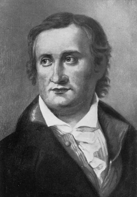
Thomas Johann Seebeck was a German physicist who worked on heat, electricity, magnetism and the science of materials. In 1821, experimenting with circuits, he found that a loop made of two different metals, with its two joints at different temperatures, deflected a compass needle placed near it: a current was flowing, driven by the difference in temperature alone. Seebeck himself thought he had found a way to make magnetism directly from heat, and called it “thermomagnetism”; others soon showed that the needle turned because of an electric current. The Seebeck effect showed for the first time a direct link between heat and electricity. It is the basis of the thermocouples used everywhere today to measure temperature, and of thermoelectric power generation and cooling.
15.1 Introduction
Have you ever wondered whether heat could make electricity?
The thermoelectric effect is the appearance of an e.m.f. when there is a difference of temperature across a material, or across the junctions of two materials. The electricity from such an e.m.f. is called thermoelectricity. It comes from the way heat and electric charge interact inside a conductor, and it is the foundation of the field of thermoelectrics.
The thermoelectric effect was discovered by Seebeck in 1821. It offers ways of converting energy and controlling heat that matter in renewable energy and electronics, and it is used for measuring temperature, for thermoelectric power generation and for cooling.
There are three thermoelectric effects:
- the Seebeck effect (Section 15.2): a temperature difference makes an e.m.f.;
- the Peltier effect (Section 15.5): a current makes one junction hot and the other cold;
- the Thomson effect (Section 15.6): a current along a single wire whose ends are at different temperatures gives out or takes in heat along it.
15.2 Seebeck effect
What do you think might happen if two different metals are joined and one of their junctions is heated?
When two wires of different materials are joined to form a closed loop, and the two junctions are kept at different temperatures, a small e.m.f. is set up in the circuit, and a small current flows round it in a definite direction. This is the Seebeck effect (or the thermoelectric effect, in its narrow sense). The e.m.f. is called the thermo e.m.f., and the current it drives the thermoelectric current.
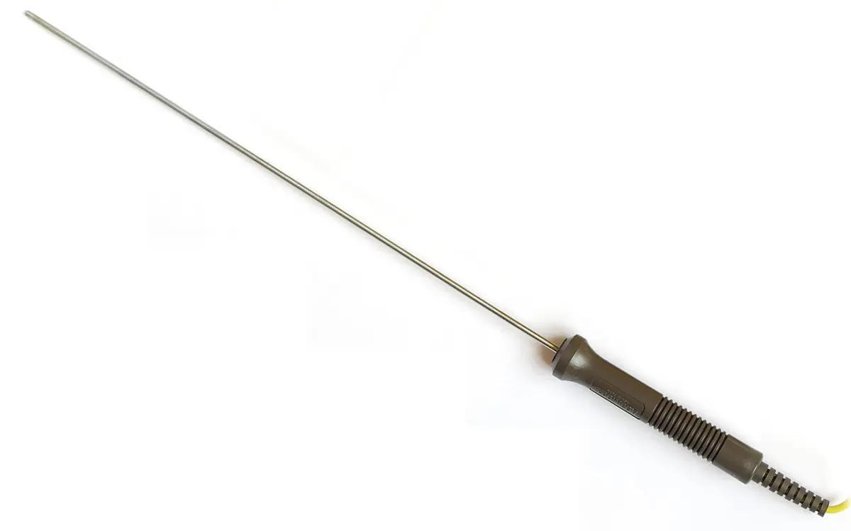
The e.m.f. is small. For a copper–iron pair with one junction in ice and the other in boiling water, it is about a millivolt; a pair often used in industry, chromel and alumel (the “type K” thermocouple), gives about 41 µV for each degree of difference, about 4 mV at 100 °C. Small, but easy to measure accurately with a potentiometer or a modern electronic meter.
Causes of the Seebeck effect
The usual textbook explanation: different metals have different numbers of free electrons per unit volume (different electron densities). When two metals are joined, free electrons diffuse from the metal with the higher electron density into the one with the lower, until the charge built up stops them. A potential difference, the contact potential, is set up at the junction.
If both junctions are at the same temperature, the contact potentials at the two junctions are equal and opposite round the loop, and no current flows. If one junction is heated, the electrons there diffuse faster and the contact potential at that junction is greater. The two no longer cancel, and the difference is a net e.m.f. round the loop: the thermo e.m.f.
A loop is made of two copper wires, one junction heated in a flame and the other kept in ice. The galvanometer in the loop shows:
Pick an answer to see why.
15.3 Thermocouples
Have you ever wondered why a thermocouple needs two different metals?
A pair of wires of two different metals, joined to form a loop that produces thermoelectricity, is called a thermocouple. The size of its e.m.f., and the direction of its current, depend on which two metals are chosen (their places in the thermoelectric series, below) and on the temperatures of the junctions. If the heating and cooling of the junctions are swapped, the current flows the other way.
A very common thermocouple, copper–iron, and the direction of its current, is shown in Figure 15.2.
Thermoelectric series
A thermoelectric series is a list of metals in order, arranged so that the order tells which way the current flows in a thermocouple made of any two of them, and roughly how big its e.m.f. is. It helps in choosing a suitable pair of metals for a thermocouple. The metals in the series are:
Antimony (Sb), Iron (Fe), Zinc (Zn), Silver (Ag), Gold (Au), Tin (Sn), Lead (Pb), Copper (Cu), Platinum (Pt), Cobalt (Co), Nickel (Ni), Bismuth (Bi)
The series is drawn up from the Seebeck effect itself, by measuring each pair. When any two metals of the series form a thermocouple:
- the current flows through the cold junction from the metal that comes earlier in the series to the one that comes later (and so through the hot junction from the later to the earlier);
- the farther apart the two metals are in the series, the larger the e.m.f. (for small temperature differences). Antimony and bismuth, at the two ends, make the strongest pair in the list.
Two rules help remember the direction:
- “Hot coffee”, Hot Cu–Fe: at the hot junction, the current flows from Cu to Fe.
- “ABC”, Antimony to Bismuth at the Cold junction: at the cold junction, the current flows from Sb to Bi.
Both agree with the series: iron comes before copper, so at the cold junction the current goes from iron to copper, and at the hot junction from copper to iron.
15.4 Variation of thermo e.m.f. with temperature
To study how the thermo e.m.f. changes with temperature, an iron–copper thermocouple can be used as in Figure 15.3. One junction is kept at a constant low temperature θc, in a mixture of ice and water. The other is put in an oil bath (oil, not water, so it can be heated well above 100 °C) with a thermometer, and heated. A sensitive galvanometer (or a potentiometer) measures the e.m.f.
When both junctions are at the same temperature θc, there is no e.m.f., and the galvanometer shows no deflection. As the oil is heated, keeping the cold junction at θc, the galvanometer shows the thermo e.m.f. increasing, becoming a maximum, then decreasing to zero, and finally reversing its direction (Figure 15.4).
- The temperature of the hot junction at which the thermo e.m.f. is a maximum is called the neutral temperature, θn. For an iron–copper thermocouple, the neutral temperature is about 270 °C. It depends only on the two metals, not on the temperature of the cold junction.
- The temperature of the hot junction at which the thermo e.m.f. becomes zero and then reverses is called the temperature of inversion, θi. It depends on the two metals and on the temperature of the cold junction.
The e.m.f. as a formula
The graph of thermo e.m.f. against temperature is a parabola. With the cold junction at 0 °C and the hot junction at θ (in °C), it is expressed as
where α and β are thermoelectric coefficients, constants for a given pair of metals. For iron–copper, α is positive and β negative; a negative β makes the parabola turn over.
Knowing α and β, θn and θi can be found.
Step 1. Neutral temperature. E is a maximum where its slope is zero:
Step 2. Temperature of inversion. E is zero where
The root θ = 0 is the cold junction’s own temperature; the other is
Step 3. A cold junction not at 0 °C. With the cold junction at θc, the e.m.f. is the difference between the two junctions’ values, . Its slope, α + βθ, is the same as before, so the neutral temperature doesn’t change. It is zero where (dividing by θ − θc), that is at . So
The neutral temperature lies halfway between the cold junction’s temperature and the temperature of inversion. The parabola is symmetric about θn: raising θc moves θi down by the same amount.
15.5 Peltier effect
When an electric current is passed through a thermocouple, heat is given out at one junction and absorbed at the other, depending on the direction of the current (Figure 15.6). This is the Peltier effect, found by the French watchmaker turned physicist Jean Charles Peltier in 1834. It is the reverse of the Seebeck effect: there a temperature difference makes a current; here a current makes a temperature difference.
The Peltier effect is reversible: when the direction of the current is reversed, the junction that was absorbing heat gives it out and the other absorbs it. This makes it quite different from Joule heating (), which heats a wire whichever way the current flows and is proportional to the square of the current; the Peltier heat is proportional to the current itself, and changes sign with it.
For a copper–iron couple, heat is absorbed (the junction cools) at the junction where the current flows from copper into iron, and given out (the junction warms) where it flows from iron into copper. This fits the Seebeck effect: in a copper–iron thermocouple the Seebeck current flows from copper to iron at the hot junction, and a current flowing that way through a junction takes in heat there. The thermocouple’s own current always tends to cool its hot junction and warm its cold one, as it should: it is turning heat into electrical energy.
Causes of the Peltier effect
When two different metals are joined, a contact potential is set up at the junction. In the copper–iron couple, iron is at the higher potential. When a current is driven round the couple:
- at the junction where the current flows from the higher-potential metal to the lower (iron to copper), the charges lose energy, which is given out as heat: the junction becomes hot;
- at the junction where the current flows from the lower-potential metal to the higher (copper to iron), the charges must gain energy, which they absorb as heat from the junction: the junction becomes cool.
In Figure 15.6a, the current flows from copper to iron at junction 1 (cooled) and from iron to copper at junction 2 (heated); in b, the other way round.
In a Peltier cooler, the direction of the current is reversed. Then:
Pick an answer to see why.
Uses of the Peltier effect
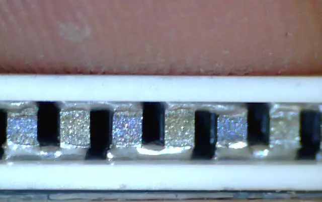
Peltier devices (thermoelectric coolers) are used for refrigeration and cooling: small car and picnic fridges, cooling the sensors of cameras and scientific instruments, keeping lasers and medical samples at a steady temperature, and water dispensers that give cold water. Reversing the current turns the same device into a heater. They have no moving parts and no refrigerant gas, so they are silent and last long, but they use more electricity than a compressor fridge for the same cooling.
15.6 Thomson effect
The third thermoelectric effect was predicted in 1851 by William Thomson (later Lord Kelvin), who worked out, from the laws of thermodynamics, that the Seebeck and Peltier effects could only be consistent if there were a third effect, and then found it by experiment.
When a current flows along a single conductor whose two ends are at different temperatures, heat is given out or absorbed along the conductor, depending on the direction of the current. This is the Thomson effect. Like the Peltier effect, it is reversible: reversing the current turns heating into cooling. Which way depends on the metal:
- In copper (and silver, zinc, antimony), a current flowing from the hot end to the cold end gives out heat, and a current from the cold end to the hot end absorbs it. The Thomson effect is said to be positive.
- In iron (and cobalt, nickel, platinum, bismuth), it is the other way round: a current from the hot end to the cold end absorbs heat, and from the cold end to the hot end gives it out. The Thomson effect is negative.
- In lead it is so small that lead is used as the reference metal when thermo e.m.f.s are measured.
The Thomson effect is why the thermo e.m.f. isn’t simply proportional to the difference of temperature: it is what makes the curve of Figure 15.4 bend. Thomson’s relations, linking all three effects, are part of thermodynamics; you will meet them in university physics.
15.7 Thermopile
A thermopile is a device for detecting and measuring heat radiation, such as the intensity of radiation from the Sun. It can also measure the high temperatures of furnaces. It works on the Seebeck effect.
Construction. A thermopile is made of a number of antimony–bismuth thermocouples joined in series, packed together in the form of a pile (Figure 15.8). One set of junctions is coated with lamp black (soot), which absorbs heat radiation well, and faces the radiation; the other set is shielded and kept at a steady, lower temperature. A sensitive galvanometer is connected across the ends of the series.
Working. When heat radiation falls on the blackened junctions, it is absorbed and their temperature rises. The difference of temperature between the two sets of junctions makes a thermo e.m.f. in each thermocouple, and since they are in series, these add up: n thermocouples give n times the e.m.f. of one. The total e.m.f. makes the galvanometer deflect. The higher the intensity of the radiation, the more the blackened junctions are warmed, and the larger the deflection.
Antimony and bismuth are used because they are at the two ends of the thermoelectric series, and so give the largest e.m.f. for each degree of difference.
Electricity from heat
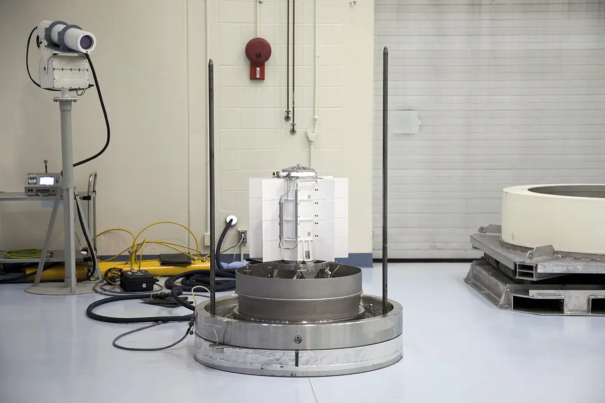
Turned to generating, the Seebeck effect makes thermoelectric generators, with no moving parts. The Voyager spacecraft, launched in 1977 and now beyond the planets, are powered by heat from decaying plutonium-238, turned into electricity by silicon–germanium thermocouples; so is the Curiosity rover on Mars. On Earth, small thermoelectric modules on wood stoves can charge a phone or a light where there is no grid. They are not efficient, a few percent to about 8 % of the heat becomes electricity, but they are silent, reliable and last for decades.
Exercise
Choose the correct option
- Which of the following statements correctly defines the Seebeck effect?
Pick an answer to see why.
- In a thermocouple, the thermoelectric e.m.f. is generated due to:
Pick an answer to see why.
- Why does the thermoelectric e.m.f. vary non-linearly with temperature in a thermocouple?
Pick an answer to see why.
- What is the main function of a thermocouple?
Pick an answer to see why.
- An iron–constantan thermocouple is used in an industrial furnace. If the hot junction is at 800 °C and the cold junction at room temperature (25 °C), what behavior of the e.m.f. is expected?
Pick an answer to see why.
- A Peltier device is used for cooling an electronic circuit. What happens when the direction of current is reversed?
Pick an answer to see why.
- The efficiency of a thermoelectric generator depends on:
Pick an answer to see why.
- A thermocouple generates an e.m.f. of 5 mV when the temperature difference between its junctions is 100 °C. What will be the e.m.f. when the temperature difference increases to 500 °C, assuming a linear relationship?
Pick an answer to see why.
- A Peltier module has a coefficient of performance (COP) of 0.5. If the input power is 10 W, what is the rate at which heat is absorbed at the cold junction?
Pick an answer to see why.
- A copper–constantan thermocouple develops a thermoelectric e.m.f. of 1 mV for a temperature difference of 10 °C. If the hot junction is at 300 °C and the cold junction at 20 °C, calculate the expected e.m.f. (taking it as proportional to the difference).
Pick an answer to see why.
Answer these questions
- a.What is the Seebeck effect?
- b.Discuss the cause of thermo e.m.f. Explain its mechanism with the help of a diagram.
- c.List the factors on which the thermo e.m.f. produced in a thermocouple depends.
- d.In a copper–iron thermocouple, the e.m.f. is related to the temperature of the hot junction (with the cold junction at 0 °C) by , with a = 14 µV/°C and b = −0.04 µV/°C². Find the neutral temperature and the temperature at which the thermo e.m.f. changes its sign.
The textbook gives b = 0.04 µV/°C², positive; with a positive b the e.m.f. would only keep rising, with no maximum and no change of sign, so the book’s numbers don’t work. Its answers, 175 °C and 350 °C, need b = −0.04 µV/°C², as here.
Answer
- a.What is thermoelectric e.m.f.?
- b.Describe the origin of thermo e.m.f., and explain how it varies with the temperature of the hot junction.
- c.The two junctions of a thermocouple are kept at 0 °C and θ °C. The thermo e.m.f. is given by volts. Find the neutral temperature and the maximum value of the thermo e.m.f.
Answer
- a.Explain the Peltier effect. How is it different from the Seebeck effect?
- b.How can you say that the Peltier effect is the converse of the Seebeck effect?
- c.Compare and contrast the Seebeck and Peltier effects, with examples and applications.
- d.The e.m.f. produced by a thermocouple is , where a = 25 µV/°C and b = 0.01 µV/°C². Calculate the e.m.f. when T = 100 °C.
Answer
- a.Define neutral temperature and temperature of inversion of a thermocouple. How are they determined?
- b.On what does the temperature of inversion depend?
- c.The junctions of a nickel–copper thermocouple are kept at 0 °C and 100 °C. Find the Seebeck e.m.f. produced, using , with α = 16.3 × 10⁻⁶ V/°C and β = −0.042 × 10⁻⁶ V/°C² for this couple.
Answer
- a.Discuss the principle and construction of a thermocouple.
- b.How is it used to measure temperature? How are thermocouples used for measuring temperature in industry? List their advantages and limitations.
- c.A thermocouple has its neutral temperature at 270 °C. If the cold junction is at 30 °C, at what temperature will the e.m.f. become zero again (the temperature of inversion)?
Answer
- a.Discuss the materials used in common thermocouples, and explain why they are chosen.
- b.Two metals A and B form a thermocouple. The e.m.f. is 2.8 mV when the hot junction is at 150 °C and the cold junction at 30 °C. Find the average Seebeck coefficient.
Answer
- a.Describe the working of a thermopile and its use in detecting radiation.
- b.A thermocouple gives a reading of 5 mV when its hot junction is at 200 °C. Find the e.m.f. when the hot junction is at 150 °C, assuming a linear relation.
Answer
- a.Explain the construction and calibration of a thermocouple using standard reference junctions.
- b.A thermocouple produces a thermoelectric e.m.f. of 4.5 mV when its hot junction is at 100 °C and its cold junction at 0 °C. Calculate the Seebeck coefficient.
Answer
Printable PDFs
- The unit as a book (A5) 21 pages Answers as an A4 booklet, 6 sheets
- Study notes 3 pages
- Worksheet 5 pages Answer key
- Harder practice questions 2 pages Answer key
Quiz yourself: Electricity and Magnetism, Grades 5–12 →
Practice every question in the book, and keep track of the ones you miss →
A companion to your textbook, not a replacement for it: study from the book your school uses, and where the two differ, follow your teacher. Found a mistake? Please tell us.