
Hold a fridge magnet against an aluminium pressure cooker and it slides off; hold it against the steel plate on the cooker’s base, the plate that lets it work on an induction stove, and it clings. Hold it near a copper coin, a plastic comb or a drop of water and nothing seems to happen at all. Yet every one of these materials does answer a magnet, in its own way. In this unit you will see why.
Every atom holds tiny magnets: its electrons, each spinning and moving round the nucleus. How those tiny magnets respond to a field sorts all materials into three kinds: diamagnetic, pushed weakly out of a field; paramagnetic, pulled weakly in; and ferromagnetic, like iron, pulled in strongly, because its atomic magnets line up together in regions called domains. You will meet the quantities that describe a material in a field (H, I, B, μ and χ), the loop that B traces in iron as the field goes up and down, which decides what makes a good transformer core and what makes a good permanent magnet, and the Earth’s own field.
17.1 History
People have known for over two thousand years that some stones attract iron, but what makes a magnet was understood only in the last two hundred.
Chinese legends tell of direction-finding devices as early as about 2600 BC, but there is no written evidence for them. Chinese writings from about the 4th century BC describe the lodestone attracting iron, and by the 11th century AD the Chinese scholar Shen Kuo described a magnetized needle that points north and south, and noticed that it points a little away from true north.
The name magnet is usually traced to Magnesia, where the iron ore magnetite (Fe₃O₄), the natural magnet or lodestone, was found: either the region of Magnesia in Greece or a city of the same name in Asia Minor (now Turkey). The Greeks knew of it by about 600 BC; the philosopher Thales is said to have thought the stone had a soul, since it could move iron. The Magnetes, the people who lived in Magnesia, gave their name to the region, so the second story of the word’s origin, that it comes from a Greek tribe called the Magnetes, leads to the same place.
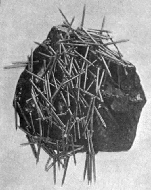
The Roman poet Lucretius (about 99–55 BC) described the magnet in his long poem De Rerum Natura (“On the Nature of Things”): a lodestone can hold a chain of iron rings, each hanging from the one above. Long before him, the Greek philosopher Plato had Socrates say: “There is a divinity moving you, like that contained in the stone which Euripides calls a magnet … This stone not only attracts iron rings, but also imparts to them a similar power of attracting other rings.” The Roman writer Pliny (AD 23–79) told the legend of a shepherd named Magnes whose iron-nailed shoes stuck to the rock on which he walked.
The study of magnetism became a science with Peter Peregrinus (1269), who named the poles of a magnet and found that a broken magnet becomes two magnets; William Gilbert (1600), who showed that the Earth itself is a great magnet; Hans Christian Oersted (1820), who found that a current makes a magnetic field; and André-Marie Ampère, Jean-Baptiste Biot and Félix Savart, Humphry Davy, William Wollaston and Michael Faraday, who worked out the laws of electromagnetism in the years after.
Which of these did William Gilbert show in 1600?
Pick an answer to see why.
17.2 A few terms
To describe how a material behaves in a magnetic field, we need a few quantities: the field applied to it, how strongly it becomes magnetized, and the field that results.
Induced magnetism and the magnetizing field
When a piece of a magnetic substance, such as iron, is placed in a magnetic field, it becomes a magnet. The magnetism produced in it this way is called induced magnetism, and the process is called magnetic induction. (“Induced” means caused by the influence of something else, without direct contact.) The field that magnetizes the substance placed in it is called the magnetizing field.
This is why a magnet picks up an unmagnetized iron nail: the magnet’s field makes the nail a magnet, with its nearer end an opposite pole, and opposite poles attract. The nail can then pick up a pin, which becomes a magnet in turn, the chain of rings that Lucretius described.
Magnetic intensity H
The strength of the magnetizing field is called the magnetic intensity (or magnetizing field strength), H. It describes the field that the currents or magnets apply to a material, apart from the material’s own response. Its SI unit is the ampere per meter (A/m); in the older CGS system it is the oersted (1 Oe ≈ 79.6 A/m).
The easiest place to see H is inside a long solenoid of n turns per meter carrying a current I:
whatever is inside the solenoid, air or iron. The current sets H; the material decides what B results. In air (or a vacuum), B and H are simply proportional:
In the older way of describing magnetism by poles, H at a point is defined as the force on a unit north pole placed there, in the direction a free north pole would move. Its direction at each point is along the magnetic line of force through that point, the line whose tangent everywhere gives the direction of the field (Unit 16).
Pole strength
A magnet’s north pole and its south pole are equally strong but opposite in kind. Pole strength, m, says how strong each pole is: a north pole has strength +m, a south pole −m. In SI, pole strength is measured in ampere meters (A m), and a pole of strength m in a field B feels a force F = mB. A magnet’s poles always come in pairs: break a magnet and each piece has a north and a south pole.
Magnetic dipole moment
A bar magnet, with its north pole and its south pole a fixed distance apart, is a magnetic dipole. Its magnetic dipole moment M tells how strong the magnet is and which way it points: it is a vector pointing from the S pole to the N pole inside the magnet.
For a bar magnet, the dipole moment is the strength of either pole times the distance between the poles:
where 2l is the magnetic length, the distance between the poles. The poles of a real bar magnet lie a little inside its ends, so its magnetic length is somewhat shorter than the bar (about 0.85 of it is a common figure). The unit of M is the ampere meter squared (A m²).
For a current loop, as you saw in Unit 16, a flat loop of area A carrying a current I is a magnetic dipole too, with
along the loop’s normal (the way the right-hand grip rule gives from the current). For a coil of N turns, . Both are in A m², the same unit: a current loop and a bar magnet are the same kind of thing as far as their fields are concerned.
A dipole in a uniform field
Put a bar magnet in a uniform field B, its moment M at an angle θ to the field (Figure 17.2 shows the moment). The N pole is pushed along the field with a force mB, and the S pole the opposite way with an equal force mB. The two forces are equal and opposite, so there is no net force, but they act along different lines: a couple. The perpendicular distance between their lines is 2l sin θ, so the torque is
This is the same law as for a coil in Unit 16. The torque turns the magnet towards the field: it is largest (MB) when the magnet is at right angles to the field and zero when it lies along it. That is why a compass needle settles along the field.
Intensity of magnetization I
A magnetized piece of material is full of tiny magnetic moments. The intensity of magnetization, I, measures how strongly it is magnetized: it is the magnetic moment per unit volume,
where M is the total magnetic moment developed in a specimen of volume V.
For a bar of cross-sectional area A and magnetic length 2l, with poles of strength m, the volume is V = A × 2l, so
So the intensity of magnetization is also the pole strength per unit area of cross-section. Its unit is (A m²)/m³ = A/m, the same as H’s. (Many books write the magnetization as M; here M is the dipole moment, so the magnetization is I.)
Magnetic induction B
Put a soft-iron bar in a uniform magnetizing field, as in Figure 17.3. The iron becomes a magnet at once: its left end, where the field enters, becomes an S pole, and its right end, where the field leaves, an N pole. The magnetized iron makes a field of its own, drawn in Figure 17.3a. Beyond its ends, in the regions A and B, the iron’s own field points the same way as the magnetizing field and strengthens it. Beside it, in the regions C and D, the iron’s field points the other way and weakens it. The resultant field (Figure 17.3b) is drawn into the iron: the lines bend inwards and crowd through it.
The lines of force inside a magnetic substance are called lines of induction. The magnetic induction B (the magnetic flux density of Unit 16) in the substance is the number of lines of induction crossing unit area at right angles. Its SI unit is the tesla (T), which is the weber per square meter; in the CGS system it is the gauss (G), the maxwell per square centimeter, and 1 T = 10⁴ G.
The induction in the specimen has two sources:
- i.the magnetizing field H, and
- ii.the specimen’s own magnetization I.
In SI units both are in A/m, and each contributes μ₀ times itself to B:
Magnetic permeability μ
Magnetic permeability measures how easily a material lets a magnetic field form in it: how much induction B results from a given magnetizing field H. It is defined as the ratio of the magnetic induction to the magnetizing field:
Its unit is T/(A/m) = T m/A (the same as the henry per meter, H/m). The higher a material’s permeability, the more B a given H produces in it: iron, of high permeability, gathers the field lines into itself, as in Figure 17.3b. In a vacuum, μ = μ₀ = 4π × 10⁻⁷ T m/A.
Relative permeability μr
The relative permeability of a material is the ratio of its permeability to that of a vacuum:
It has no unit. It tells how many times larger B is in the material than it would be in a vacuum for the same H. For air, μr is 1.0000004; for soft iron, it is in the thousands.
Magnetic susceptibility χ
Magnetic susceptibility measures how easily a material becomes magnetized in a field. It is the ratio of the intensity of magnetization to the magnetizing field:
Since I and H are both in A/m, χ has no unit. It is negative for a material magnetized against the field, positive for one magnetized along it.
Relation between μr and χ
The relative permeability and the susceptibility are two ways of saying the same thing.
Step 1. Start from B. .
Step 2. Write I in terms of H. From , , so
Step 3. Divide by H. , and B/H is the permeability μ:
Step 4. Divide by μ₀. , so
A material with χ slightly below zero has μr slightly below 1; one with a large χ has a large μr.
The intensity of magnetization of a material is 300 A/m in a magnetizing field of 6 × 10⁵ A/m. Its susceptibility is:
Pick an answer to see why.
17.3 Classification of magnetic substances
Every material responds to a magnetic field, though most so weakly that only a strong magnet shows it. By the way they respond, substances fall into three groups: diamagnetic, paramagnetic and ferromagnetic.
The difference starts inside the atom. Each electron is a tiny magnet, from its spin and from its motion round the nucleus. In most atoms the electrons are in pairs whose tiny magnets cancel; an atom with unpaired electrons has a magnetic moment of its own.
Diamagnetic substances
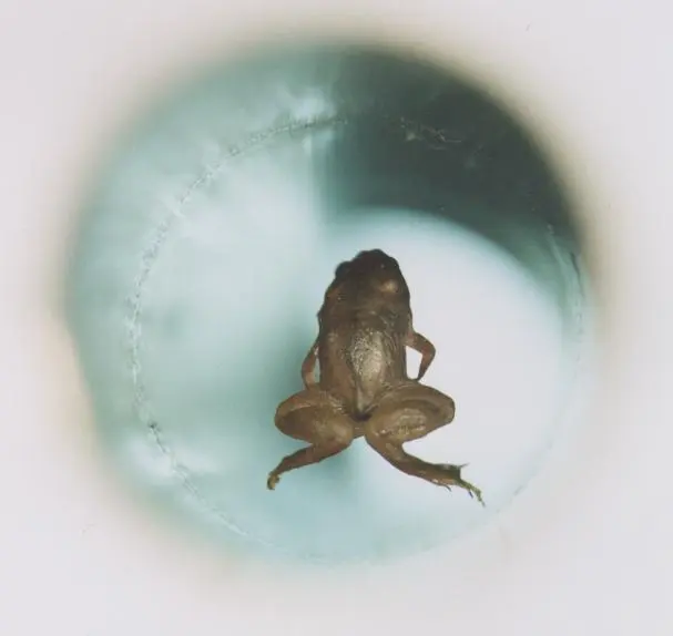
Diamagnetic substances are those which, placed in a magnetic field, are weakly repelled by it: they are feebly magnetized in the direction opposite to the magnetizing field. Copper, zinc, bismuth, antimony, mercury, silver, gold, water and most organic materials are diamagnetic.
Diamagnetism happens in every atom. When a field is applied, it changes the motion of the electrons round the nucleus a little, and by the same rule as Lenz’s law (Unit 18) the change makes a magnetic moment that opposes the field. In atoms whose electrons are all paired, this is the only response, so the substance is pushed weakly away from a strong field.
Their properties:
- i.A rod of a diamagnetic substance hung between the poles of a strong magnet settles at right angles to the field (Figure 17.5a).
- ii.They are magnetized in the direction opposite to the applied field.
- iii.They are weakly repelled by a magnet: they move from the stronger to the weaker part of a field.
- iv.Their susceptibility is small and negative, about −10⁻⁵ (bismuth’s, one of the largest, is about −1.7 × 10⁻⁴), and it does not depend on temperature.
- v.Their relative permeability is slightly less than 1.
- vi.They show no hysteresis: the magnetization disappears as soon as the field is removed.
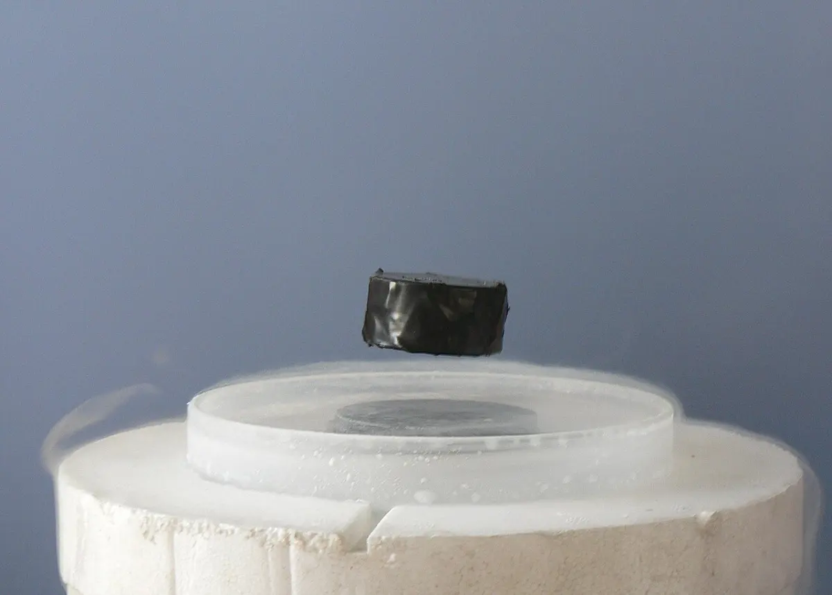
- vii.Superconductors are perfect diamagnets: χ = −1 and μr = 0. They push a magnetic field out of themselves entirely (the Meissner effect, Figure 17.4a), strongly enough to float above a magnet.
- viii.Examples: bismuth, antimony, copper, mercury, silver, zinc, gold and water.
Paramagnetic substances
Paramagnetic substances are those which, placed in a magnetic field, are weakly attracted by it: they are feebly magnetized in the direction of the magnetizing field. Aluminium, platinum, sodium, potassium, magnesium and oxygen are paramagnetic.
Their atoms have unpaired electrons, so each atom is a tiny permanent magnet. With no field, heat keeps these tiny magnets pointing every way, and they cancel. A field turns them a little towards itself, against the jiggling of the atoms, so the substance is magnetized weakly along the field (and its own diamagnetism, much weaker, is outweighed).
Their properties:
- i.A rod of a paramagnetic substance hung between the poles of a magnet settles along the field (Figure 17.5b).
- ii.They are magnetized along the field.
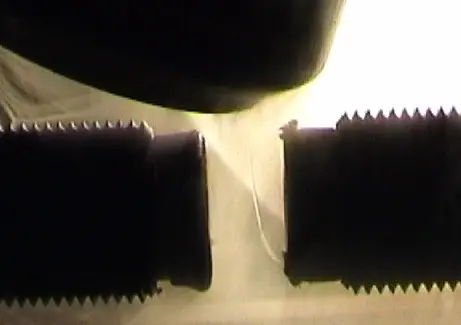
- iii.They are weakly attracted by a magnet: they move from the weaker to the stronger part of a field. A paramagnetic liquid in a U-tube rises in the limb placed between the poles (Figure 17.8).
- iv.Their relative permeability is slightly greater than 1.
- v.Their susceptibility is small and positive, about 10⁻⁵ to 10⁻³ (aluminium’s is about 2 × 10⁻⁵, platinum’s about 2.6 × 10⁻⁴).
- vi.They show no hysteresis.
- vii.Examples: aluminium, platinum, sodium, potassium, magnesium and oxygen.
- viii.Their susceptibility is inversely proportional to the absolute temperature:
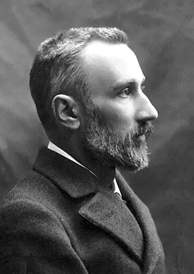
where C is a constant for the substance, its Curie constant. This is Curie’s law, found by Pierre Curie in 1895. The hotter the substance, the harder its atoms jiggle and the less a field can line up their tiny magnets.
Ferromagnetic substances
Ferromagnetic substances are those which are strongly attracted by a magnet: they are strongly magnetized in the direction of the magnetizing field. Iron, cobalt, nickel, gadolinium and their alloys, such as steel, are ferromagnetic.
Their properties:
- i.A rod of a ferromagnetic substance hung near a magnet turns quickly and settles along the field.
- ii.They are strongly magnetized along the field.
- iii.They are strongly attracted by a magnet.
- iv.Their susceptibility decreases as the temperature rises. Above the Curie temperature TC the substance is paramagnetic, with , the Curie–Weiss law.
- v.Their relative permeability is much larger than 1: hundreds to many thousands.
- vi.Their susceptibility is large and positive.
- vii.They show hysteresis (Section 17.5).
- viii.Examples: iron, cobalt, nickel and gadolinium.
| Diamagnetic | Paramagnetic | Ferromagnetic | |
|---|---|---|---|
| In a field | weakly repelled | weakly attracted | strongly attracted |
| Magnetized | against the field, feebly | along the field, feebly | along the field, strongly |
| Susceptibility χ | small, negative (about −10⁻⁵) | small, positive (10⁻⁵ to 10⁻³) | large, positive (hundreds to thousands) |
| Relative permeability μr | slightly less than 1 | slightly more than 1 | much more than 1 |
| χ and temperature | does not depend on it | χ = C/T (Curie’s law) | falls as T rises; paramagnetic above TC |
| Hysteresis | no | no | yes |
| Examples | Bi, Cu, Ag, Hg, water | Al, Pt, Na, O₂ | Fe, Co, Ni, Gd |
A substance has a relative permeability of 0.99998. It is:
Pick an answer to see why.
17.4 Ferromagnetism on the basis of domain theory
Why is iron so different from aluminium? In both, the atoms are tiny magnets. In iron, cobalt and nickel, neighboring atomic magnets act on each other so strongly (by an effect of quantum physics called the exchange interaction) that they line up with one another of their own accord, even with no field around.
The domain theory explains ferromagnetism this way:
- A ferromagnetic material is divided into small regions called domains, each perhaps a hundredth to a tenth of a millimeter across but holding many trillions of atoms. In each domain, all the atomic magnetic moments are lined up: each domain is magnetized to saturation, a strong little magnet.
- With no external field, the domains point in different directions (Figure 17.11a). Their moments cancel, and the piece as a whole is not a magnet.
- In a weak field, the walls between domains move: the domains whose moments point along the field (or nearly along it) grow, at the expense of the others (Figure 17.11b). The piece becomes magnetized along the field.
- In a strong field, the remaining domains turn until all the moments point along the field (Figure 17.11c). The piece is magnetized as much as it can be: saturated.
- When the material is heated, its atoms jiggle harder and the lining up breaks down; at the Curie temperature the domains are gone and the material becomes paramagnetic.
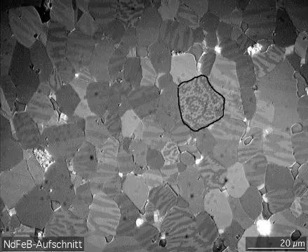
The domains explain what the other two groups lack. Moving a domain wall is not perfectly smooth: the walls catch on impurities and flaws in the crystal and jump past them. So when the field is removed, the walls do not all go back: some magnetization remains. That is the origin of hysteresis, the subject of the next section, and the reason a steel needle can become a permanent magnet.
| Metal | Curie temperature |
|---|---|
| gadolinium | about 20 °C (293 K) |
| nickel | about 360 °C |
| iron | 770 °C (1043 K) |
| cobalt | about 1120 °C |
In an unmagnetized iron nail, the domains:
Pick an answer to see why.
17.5 Magnetic hysteresis
Magnetize a piece of iron, then switch the field off. Does the iron go back to how it was? Not quite: it remembers.
Hysteresis means “lagging behind”. The lagging of the magnetic induction B behind the magnetizing field H, when H is changed, is called magnetic hysteresis.
The hysteresis loop
Take an unmagnetized ferromagnetic specimen (an iron ring wound with a coil, for instance) and change H, by changing the current, through a full cycle while measuring B. Figure 17.13 shows the graph of B against H.
- i.As H is increased from zero, B increases, along the curve Oa, at first slowly, then fast as the domains grow, then slowly again.
- ii.Increasing H further, B increases until it reaches saturation at a: all the domains point along the field, and B hardly changes any more.
- iii.Now decrease H. B decreases too, but it does not come back along aO: at H = 0, B is not zero but Ob. The material keeps some magnetism. This is called the retentivity (or remanence, or residual magnetism), Ob.
- iv.Reverse H and increase it the other way. B decreases further, and at c (H = −Oc) the material is fully demagnetized, B = 0. The reverse field needed to bring B to zero, Oc, is called the coercivity (or coercive force).
- v.Increasing the reverse field saturates the material the other way, at d. Bringing H back to zero leaves B = −Oe at e; a field Of the first way brings B to zero at f, and B returns to saturation at a. The closed curve abcdefa is the hysteresis loop.
The point O is never reached again unless the material is demagnetized, for example by an alternating field that dies away slowly. B always lags behind H: on the way down it is higher than on the way up.
Retentivity, coercivity and the loop’s area
- Retentivity (Ob): the magnetic induction left in the material when the magnetizing field is reduced to zero. It tells how much magnetism the material keeps.
- Coercivity (Oc): the reverse magnetizing field needed to bring the magnetic induction to zero. It tells how hard it is to demagnetize the material.
- Hysteresis loss: in every cycle, the material is magnetized one way, demagnetized and magnetized the other way, and the domain walls jumping past flaws waste energy as heat. The energy spent per unit volume in one complete cycle is equal to the area of the hysteresis loop:
On a B–H graph, the area has the unit (A/m) × T = J/m³. A transformer core is taken round its loop 50 times a second by the mains, so its loss each second is 50 times the loop’s area times the core’s volume.
Soft and hard magnetic materials
The shape of the hysteresis loop depends on the material (Figure 17.14).
- Soft iron (and other soft magnetic materials): a tall, narrow loop with a small area. It reaches a high B in a small H (high permeability), is easily demagnetized (low coercivity), and wastes little energy in each cycle. Ideal for transformer cores, generator and motor cores and electromagnets, which must be magnetized and demagnetized quickly and often. Silicon steel (iron with about 3 % silicon) and mumetal (a nickel–iron alloy) also have narrow loops; silicon steel is used for most transformer cores.
- Steel (and other hard magnetic materials): a shorter, wide loop with a large area. It has a high coercivity and a fairly high retentivity, so once magnetized it is very hard to demagnetize. Its large hysteresis loss does not matter for a permanent magnet, which is never taken round its loop. Ideal for permanent magnets: cobalt steel, chromium steel, tungsten steel and alnico (iron with aluminium, nickel and cobalt, and a little copper). Today’s strongest permanent magnets are neodymium magnets (an alloy of neodymium, iron and boron, made since the 1980s), in earphones, phone speakers, electric-car motors and wind turbines.
So the material is chosen by its loop:
| Use | It needs | Material |
|---|---|---|
| permanent magnet | high retentivity, high coercivity (a wide loop) | steel, alnico, neodymium–iron–boron |
| electromagnet | high permeability, low retentivity, low coercivity | soft iron |
| transformer core | high permeability, low coercivity, small loop area | silicon steel, soft iron |
A material is wanted for the core of a transformer. Its hysteresis loop should be:
Pick an answer to see why.
17.6 The Earth’s magnetic field
A compass works because the Earth is a magnet, as Gilbert showed in 1600. The exercise below asks about it, so here is what you need.
The Earth as a magnet
Near the Earth’s surface, its field is much like that of a huge bar magnet at its center, tilted about 10° from the Earth’s axis (Figure 17.15). The field lines leave the southern hemisphere and enter the northern one: near the geographic North Pole there is a magnetic S pole, which is why the north pole of a compass needle is drawn there.
There is no magnet inside the Earth: the center is far hotter than iron’s Curie temperature. The field is made by electric currents in the Earth’s outer core, a layer of molten iron 2,900 km down, kept moving by heat flowing out of the core and stirred by the Earth’s rotation. This self-sustaining process is called the geodynamo. It changes slowly: the magnetic poles wander tens of kilometers a year, and over millions of years the field has reversed many times, the last time about 780,000 years ago.
Declination, dip and the horizontal component
At any place, three quantities describe the Earth’s field, its elements (Figure 17.16):
- Declination D: the angle between the geographic meridian (the north–south line through true north) and the magnetic meridian (the vertical plane in which a freely turning compass needle settles). It is how far a compass points away from true north.
- Dip (or inclination) δ: the angle the total field makes with the horizontal, in the magnetic meridian. A needle free to turn in a vertical plane (a dip needle) shows it. The dip is 0° at the magnetic equator and 90° at the magnetic poles.
- Horizontal component BH: the part of the field along the ground, in the magnetic meridian. It is what turns an ordinary compass.
If the total field is B, its horizontal and vertical parts are
so that
At a magnetic pole, δ = 90°, so BH = B cos 90° = 0: a compass there has no horizontal field to turn it, and points nowhere in particular. At the magnetic equator, δ = 0 and the field is all horizontal.
At a place where the angle of dip is 60°, the horizontal component of the Earth’s field is 20 µT. The total field is:
Pick an answer to see why.
Exercise
Choose the correct option
- A permanent magnet is made from which of these substances?
Pick an answer to see why.
- At a certain place the horizontal component of the Earth’s magnetic field is B₀ and the angle of dip is 45°. What is the total intensity of the field at that place?
Pick an answer to see why.
- Where does the Earth’s magnetic field have no horizontal component?
Pick an answer to see why.
- A magnetic field can be detected because it:
Pick an answer to see why.
- What happens to the susceptibility of a ferromagnetic substance when its temperature is increased?
Pick an answer to see why.
- The magnetic susceptibility of a diamagnetic substance is:
Pick an answer to see why.
- Magnetic lines of force:
Pick an answer to see why.
- The temperature above which a ferromagnetic material becomes paramagnetic is called the:
Pick an answer to see why.
- What is the cause of the Earth’s magnetic field?
Pick an answer to see why.
- A magnet of dipole moment 2 A m² is deflected through 30° from the magnetic meridian. The deflecting torque needed is (BH = 0.4 × 10⁻⁴ T):
Pick an answer to see why.
- The hysteresis loop of a ferromagnetic material becomes narrower when:
Pick an answer to see why.
- The loops in the figure above belong to two materials. Magnets for electric generators, transformer cores and electromagnet cores are to be made from them. It is proper to use:
Pick an answer to see why.
Answer these questions
- a.A ferromagnetic substance becomes paramagnetic above its Curie temperature. Explain why.
- b.The magnetic intensity at a point is 1000 A/m. Find the magnetic induction in a material of magnetic susceptibility 1272 placed there.
Hint
Answer
- a.Define relative permeability and magnetic susceptibility.
- b.Establish the relation between magnetic susceptibility and relative permeability.
- c.What properties should a substance have to make a permanent magnet?
Hint
Answer
- a.Define retentivity and coercivity.
- b.Two hysteresis loops, a and b, are shown in Figure 17.18.
- i.Which best represents the hysteresis loop of soft iron? Give a reason for your answer.
- ii.Which material, a or b, is more suitable for a transformer core, and which for a permanent magnet? Justify your answer.
- iii.Name the physical quantity represented by the area of the hysteresis loop.
Hint
Answer
- a.i. Define magnetic hysteresis. Sketch and label a typical hysteresis loop for a ferromagnetic material.
- ii.Explain the significance of the following with reference to the hysteresis loop: 1. retentivity, 2. coercivity, 3. hysteresis loss.
- iii.How are these properties used in choosing materials for permanent magnets and transformer cores?
- b.i. Distinguish between diamagnetic, paramagnetic and ferromagnetic materials on the basis of 1. their magnetic susceptibility, 2. their behavior in an external magnetic field, 3. examples.
- ii.Explain why ferromagnetic materials show hysteresis but diamagnetic and paramagnetic materials do not. Use the idea of magnetic domains in your explanation.
Hint
Answer
Printable PDFs
- The unit as a book (A5) 33 pages Answers as an A4 booklet, 9 sheets
- Study notes 3 pages
- Worksheet 4 pages Answer key
- Harder practice questions 2 pages Answer key
Quiz yourself: Electricity and Magnetism, Grades 5–12 →
Practice every question in the book, and keep track of the ones you miss →
A companion to your textbook, not a replacement for it: study from the book your school uses, and where the two differ, follow your teacher. Found a mistake? Please tell us.