
Flick a switch and the room lights up before your finger has left it. Plug in the rice cooker and, half an hour later, dinner is ready. Every month someone from the electricity office reads the meter on your wall, and a bill arrives. Behind all of it is one invisible thing moving through copper wires: electric charge.
This unit follows the charge round a circuit. You will see what pushes it (e.m.f. and potential difference), what holds it back (resistance), the simple law that links them (Ohm’s law), why the bulbs in a house are joined one way and Tihar lights another, how a heater turns electricity into heat, and how to work out your family’s electricity bill yourself.
Electricity is a form of energy that travels through conducting wires. Every appliance is joined to the supply by two wires, so that the charge has a complete loop to go round: out along one wire, through the appliance, and back along the other. That loop is a circuit. Every appliance turns electrical energy into some other form of energy (light, heat, sound, motion), but not at the same rate: a heater turns far more electrical energy into heat each second than a bulb turns into light. How fast an appliance does this depends on its resistance, and a meter on the wall measures how much energy the whole house has used, which is what the bill is based on.
Electric current
What is moving?
For a current to flow, something charged must be free to move. In the activity there are two kinds of moving charge.
- In metal wires: free electrons. An atom has a positive nucleus with electrons around it. In a metal, the outermost electron of each atom is held only weakly by its nucleus, so it wanders easily from one atom to the next. These are called free electrons. A copper wire is full of them, drifting about at random. Connect a cell, and they all start drifting the same way, towards the positive terminal.
- In the salt solution: ions. Common salt (sodium chloride) breaks up in water into positive sodium ions (Na⁺) and negative chloride ions (Cl⁻), which move freely through the liquid. When the ends A and B are dipped in it, the positive ions move towards the wire joined to the negative terminal, and the negative ions towards the wire joined to the positive terminal. A solution that conducts like this is an electrolyte.
A flow of charge is an electric current. More exactly, electric current is the rate of flow of charge: how much charge passes a point in the circuit every second.
If a charge passes a point in a time , the current is
The units of charge and current
The SI unit of charge is the coulomb (C). One electron carries a tiny charge, 1.6 × 10⁻¹⁹ C, so one coulomb is the charge of about 6.25 × 10¹⁸ electrons (6 250 000 000 000 000 000 of them).
The SI unit of current is the ampere (A). One ampere is a flow of one coulomb per second:
Small currents are measured in smaller units:
- 1 milliampere (mA) = 10⁻³ A = 0.001 A
- 1 microampere (μA) = 10⁻⁶ A = 0.000 001 A
Current is measured with an ammeter, which is always connected in series in the circuit: the circuit is broken and the ammeter is put into the gap, so that all the current has to pass through it (Figure 11.6).
Which way does the current go?
In a metal wire, the electrons flow from the negative terminal of the cell, round the circuit, to the positive terminal. But a flow of negative charge one way does the same job as a flow of an equal positive charge the other way. Long before electrons were discovered, scientists had agreed to draw current as a flow of positive charge, from the positive terminal to the negative terminal. This direction, used in every circuit diagram, is called the conventional current.
Why does a copper wire conduct electricity, but a dry plastic ruler doesn’t?
Pick an answer to see why.
Which of these is not a correct way of saying “one ampere”?
Pick an answer to see why.
Electromotive force (e.m.f.) and potential difference (p.d.)
Fill two plastic bottles with water to different levels and join them at the bottom with a pipe. Water flows from the fuller bottle to the emptier one, until the levels are the same. Then it stops. To keep it flowing, you would have to keep lifting water back up into the first bottle: you would need a pump.
A circuit works the same way. Charge flows only when there is a “difference in level” between two points, and a cell is the pump that keeps the difference going.
| The water circuit | The electric circuit |
|---|---|
| Water flows from a high level to a low level. | Charge flows from the positive terminal (high potential) to the negative terminal (low potential). |
| When both levels are the same, the water stops. To keep it flowing, a pump uses energy to lift water from the low level back to the high level. | To keep charge flowing, the cell uses chemical energy to keep one terminal at a high potential (+) and the other at a low potential (−). |
| The pump provides the energy for the flow. | The chemical reaction in the cell provides the energy for the flow. |
| When the pump stops, the levels become equal and the flow stops. | When the chemical reaction stops (the cell is “dead”), there is no difference in potential, and the current stops. |
When water flows down a pipe, it loses potential energy, and that energy can do work: put a water wheel or turbine in the pipe, and it turns. In the same way, when positive charge moves from a point at high potential to a point at low potential, it gives up energy in the wires and in the appliances (the electric load), and work is done: the bulb lights, the fan turns.
How much energy a cell can give to each unit of charge tells us its potential. The positive terminal of a cell is at a higher potential and the negative terminal at a lower potential. So, for a current to flow through an appliance, one end of it must be joined to the higher potential and the other end to the lower potential of the source.
Electromotive force
Charge needs energy to flow round a circuit. Electric sources, such as generators, batteries and solar panels, provide it. A source changes some other form of energy into electrical energy: a battery changes chemical energy, a solar panel light energy, a generator kinetic energy.
The energy that a source gives to each coulomb of charge to drive it round the whole circuit is its electromotive force (e.m.f.).
Potential difference
The e.m.f. creates a potential difference between the two ends of the electric load. If end A of a bulb is joined to the positive terminal of a battery and end B to the negative terminal, then A is at a higher potential than B, and positive charge flows through the bulb from A to B. As it does, electrical energy is changed into other forms in the bulb.
The potential difference (p.d.) between two points is the energy changed into other forms when one coulomb of charge moves from one point to the other. It is commonly called the voltage.
Both e.m.f. and p.d. are energy per coulomb, so both have the same SI unit, the volt (V): 1 V = 1 J/C. Both are measured with a voltmeter, which is always connected in parallel: across the part being measured, without breaking the circuit.
When no current flows in the outside circuit, the p.d. between the cell’s terminals equals its e.m.f. That is why the first voltmeter in Figure 11.5 reads the e.m.f. When a current flows, some electrical energy is used up inside the battery itself, so the p.d. across the load is less than the e.m.f. For example, a battery of e.m.f. 3 V might give a p.d. of 2.5 V across a bulb. That means the battery gives each coulomb 3 J of energy, but the bulb changes only 2.5 J of it into heat and light; the other 0.5 J warms the battery.
| Electromotive force | Potential difference |
|---|---|
| The energy the source gives to one coulomb of charge to drive it round the whole circuit. | The energy changed into other forms when one coulomb flows between two points of the outside circuit. |
| It doesn’t depend on the resistance connected in the circuit. | It depends on the resistance connected in the circuit. |
| It is the cause of the potential difference. | It is the effect of the e.m.f. |
| It belongs to a source (cell, generator). | It exists between any two points of a circuit. |
A battery has an e.m.f. of 6 V. With a lamp lit, a voltmeter across the lamp reads 5.4 V. Where did the rest of the energy go?
Pick an answer to see why.
How are an ammeter and a voltmeter connected to measure the current through a bulb and the p.d. across it?
Pick an answer to see why.
Ohm’s law
The law
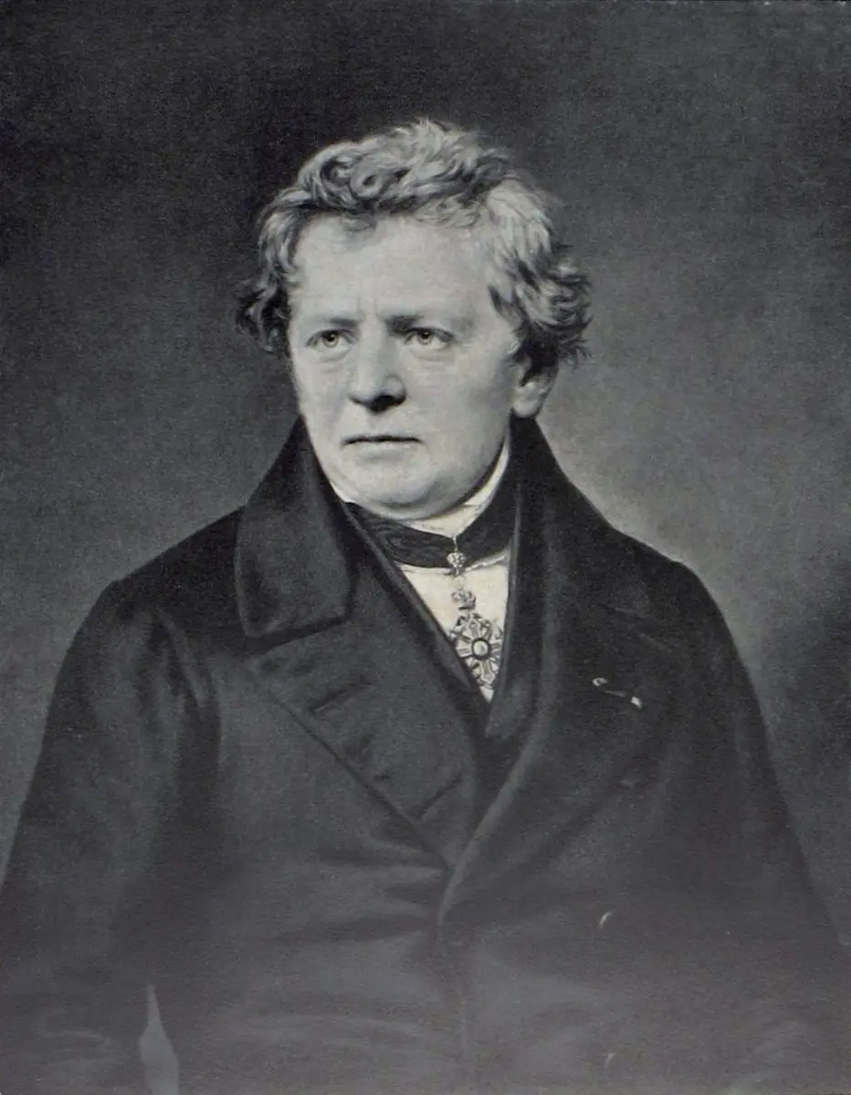
In 1827 a German schoolteacher, Georg Simon Ohm, published the relation between the potential difference across a conductor and the current through it. It is now called Ohm’s law:
The current flowing through a conductor is directly proportional to the potential difference across its ends, provided its temperature and other physical conditions stay the same.
If a current flows when the p.d. is , then
This constant is called the resistance of the conductor:
So resistance is the ratio of the potential difference across a conductor to the current through it.
Electric resistance
Join a thick copper wire and a thin copper wire of the same length, one at a time, to the same cell. Charge flows much more easily through the thick wire. Every conductor gets in the way of the current a little: the moving electrons keep bumping into the atoms of the metal, which vibrate in their places. This opposition to the flow of current is called electrical resistance.
The SI unit of resistance is the ohm, named after Georg Simon Ohm, with the symbol Ω (the Greek capital letter omega).
From Ohm’s law, , so
One ohm is the resistance of a conductor through which a current of 1 A flows when a potential difference of 1 V is applied across its ends.
The ohm in fundamental units
The ohm is a derived unit. To see which fundamental units it is made of, write and in terms of simpler quantities:
Force = mass × acceleration, and charge = current × time (), so
Acceleration has units m s⁻², so putting in the units:
The ohm contains the units of mass (kg), length (m), current (A) and time (s), so it is a derived unit.
Factors affecting resistance
The resistance of a conductor depends on four things:
- Length. Of two wires of the same thickness, the longer one has more resistance. Double the length, and the electrons must get past twice as many atoms: twice the resistance.
- Thickness (cross-sectional area). A thin wire has more resistance than a thick one. A thick wire is like a wide road: more charge can flow side by side.
- Temperature. For a metal wire, heating it increases its resistance: the hotter atoms vibrate more and get in the electrons’ way more often.
- The material. Copper and nichrome wires of exactly the same length and thickness have very different resistances: the nichrome wire’s is about 60 times larger.
For a given conductor kept in the same conditions, though, the ratio stays the same, however large is. That is Ohm’s law again.
Which wire has the largest resistance? (All are copper, at room temperature.)
Pick an answer to see why.
Combination of resistors
A resistor is anything in a circuit that has resistance: a bulb, a heater element, or the small striped component inside a radio. Two or more of them can be joined in two basic ways, in series and in parallel.
Series combination of resistors
In a series combination, the resistors are joined end to end, one after another, and the first and the last are connected to the source.
- There is only one path for the current, so the same current flows through every resistor.
- The p.d. of the source is shared among the resistors.
- If one resistor breaks (a bulb fuses), the circuit is broken and they all stop working.
- Separate switches can’t be used for each one.
Older strings of small decoration bulbs, the kind hung on houses for Tihar (Deepawali), were joined in series: if one bulb fused, the whole string went dark, and you had to test bulb after bulb to find the dead one.
Let the resistances be and , the p.d. across them and , and the total resistance of the combination . Since the p.d. is shared,
By Ohm’s law each p.d. is the current times the resistance, and the current is the same everywhere:
Dividing by :
In a series combination, the total resistance is the sum of the individual resistances. It is always larger than the largest of them.
Parallel combination of resistors
In a parallel combination, two or more resistors are each connected separately across the source, between the same two points.
- Every resistor has the same potential difference across it.
- There is a separate path for the current through each resistor, so the current is divided among them.
- If one resistor breaks, current still flows through the others and they keep working.
- Each one can have its own switch.
This is how the lights, fans and sockets in a house are wired.
Let the currents through the resistors be and , and the total resistance . Since the current divides,
By Ohm’s law, for each, with the same everywhere:
Dividing by :
In a parallel combination, the reciprocal of the total resistance is the sum of the reciprocals of the individual resistances. The total is always smaller than the smallest of them: every extra path makes it easier for the current to get through, like opening more ticket counters at a bus park.
Two identical bulbs are joined in series to a cell. One bulb fuses. What happens to the other?
Pick an answer to see why.
A house has a TV, a fan and five lights all switched on. Someone switches on a heater as well. What happens to the total resistance of the house’s circuit?
Pick an answer to see why.
Heating effect of electric current
When a current flows through a resistance, the electrons keep colliding with the atoms of the conductor, and the energy they carry is turned into heat. The changing of electrical energy into heat in an electric load is called the heating effect of electric current.
Electric heaters, kettles, immersion rods, irons and rice cookers all work by the heating effect. Their heating element is made of nichrome, an alloy (mixture) of nickel and chromium. Nichrome suits the job because:
- its resistance is high, so a short coil turns a lot of electrical energy into heat quickly;
- its melting point is high, about 1400 °C, so it can glow red-hot without melting;
- it doesn’t oxidize (rust or burn) even when red-hot in air, at 900 °C and more, because a thin, tough layer of chromium oxide forms on its surface and protects it.
A filament bulb uses a very thin wire of tungsten, which melts at 3422 °C, the highest melting point of any metal. It is heated to about 2500 °C, so hot that it gives out light as well as heat. To stop it burning up, the glass bulb holds no oxygen: it is filled with an unreactive gas such as argon, or emptied of air.
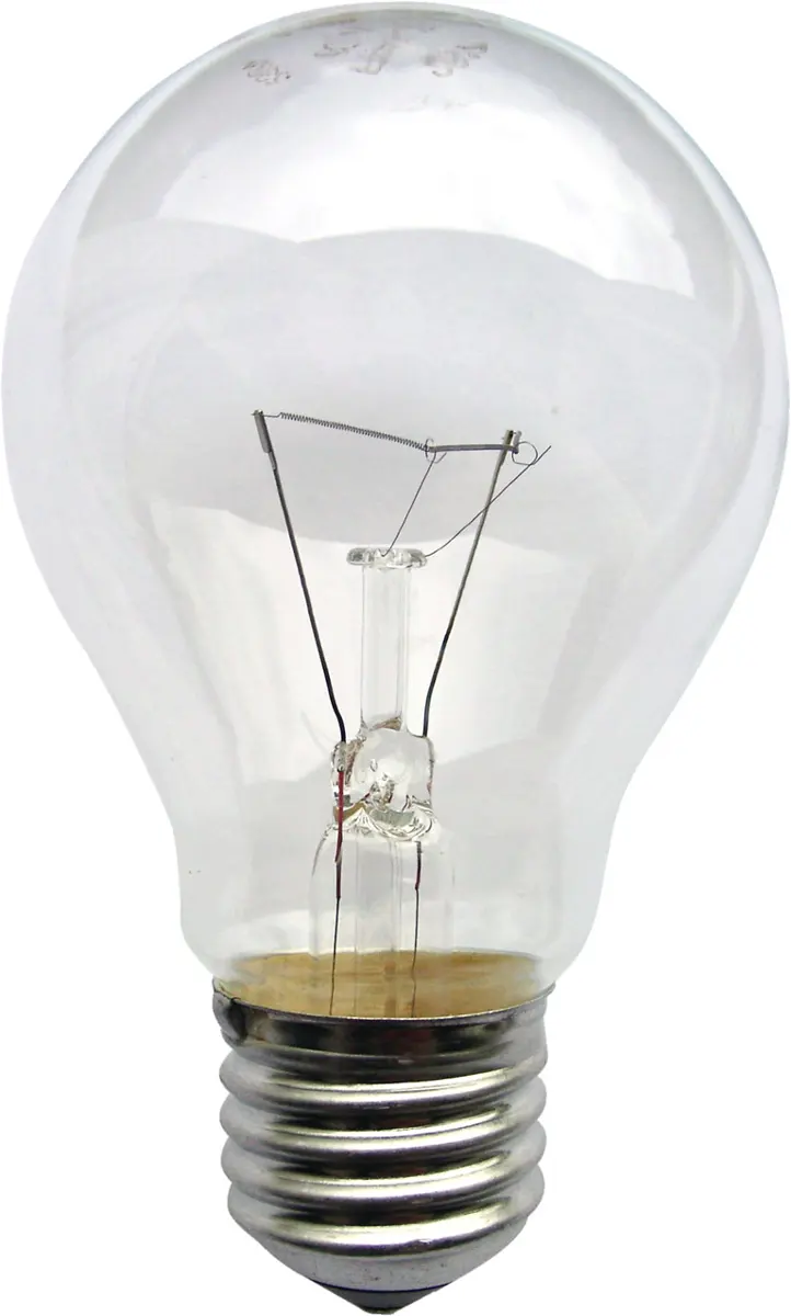
The heating effect also depends on the current. A sudden rise in the supply’s voltage, or too many appliances on one wire, can make the current so large that the wires themselves overheat and their plastic covering melts. That is why every house has a fuse or circuit breaker (MCB): a safety device that cuts off the current if it gets too large.
Which property is not a reason for using nichrome in a heating element?
Pick an answer to see why.
Electric power
An electric load changes electrical energy into other forms. The energy changed into another form in one second is the power of the appliance.
Its SI unit is the watt (W): 1 W = 1 J/s. 1 kilowatt (kW) = 1000 W.
The energy is changed because charge flows through the appliance across the p.d. between its ends. From the definition of potential difference,
which is the electrical energy changed by the appliance. Putting this into equation (1):
and since is the current ,
Power = potential difference × current.
A phone charger is rated 5 V, 2 A. What is its power?
Pick an answer to see why.
Electricity consumption
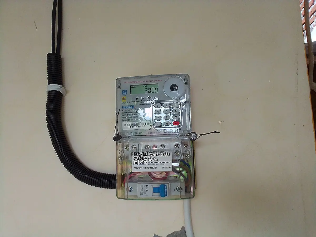
The electrical energy used by appliances is called electricity consumption. It is measured by the electric meter (energy meter) on the wall of every house.
Energy is power × time:
In joules, the numbers get huge: a 1000 W heater uses 3 600 000 J in one hour. So electricity is sold in a bigger unit, the kilowatt-hour (kWh): the energy used by an appliance of power one kilowatt in one hour. In everyday speech, one kilowatt-hour is simply called one unit.
How much energy an appliance uses depends on two things: its power and how long it is used. A 10 W LED bulb left on for 100 hours uses as much (1 unit) as a 1000 W heater in one hour.
How many units of electricity does a 2000 W heater use in 30 minutes?
Pick an answer to see why.
Electricity bill
To find out how much electricity a house used in a month, the meter reader notes the reading on the meter and subtracts last month’s reading. The difference is the number of units used. The bill is the number of units multiplied by the price of one unit.
To work it out from the appliances instead, use
where is the power of each appliance in kilowatts, is the number of appliances of that kind, and is the time each one is used in hours. The answer is in kWh (units).
Project work
Exercise
1. Select the best answers
(i) Which of the graphs in Figure 11.17 shows Ohm’s law?
Pick an answer to see why.
(ii) What is the heating element of an electric heater made of?
Pick an answer to see why.
(iii) Why are the electric loads in a house connected in parallel?
Pick an answer to see why.
(iv) Bulb A is marked 220 V, 0.5 A and bulb B is marked 220 V, 0.45 A. When both work at their full rating, which statement is true?
Pick an answer to see why.
(v) In the circuit of Figure 11.18, what is the value of ?
Pick an answer to see why.
(vi) How much electrical energy does a 1 kW heater change in 1 hour?
Pick an answer to see why.
2. Differentiate between
Electromotive force and potential difference
Answer
| Electromotive force (e.m.f.) | Potential difference (p.d.) |
|---|---|
| The energy a source gives to each coulomb of charge to drive it round the whole circuit. | The energy changed into other forms when each coulomb flows between two points of the outside circuit. |
| It doesn’t depend on the resistance in the circuit. | It depends on the resistance in the circuit. |
| It is the cause. | It is the effect of the e.m.f. |
| It belongs to a source: a cell, a battery, a generator. | It exists between any two points of a circuit. |
| It is a little larger than the p.d. across the load when a current flows. | It is a little less than the e.m.f. when a current flows. |
Parallel combination and series combination of electric loads
Answer
| Parallel combination | Series combination |
|---|---|
| Each load is connected separately across the source. | The loads are joined end to end, one after another. |
| The p.d. across every load is the same. | The p.d. of the source is shared among the loads. |
| The current divides among the loads. | The same current flows through every load. |
| There is a separate path for the current through each load. | There is only one path for the current. |
| If one load fails, the others keep working. | If one load fails, all of them stop. |
| Each load can have its own switch. | Separate switches can’t be used. |
| Total resistance: (less than the smallest). | Total resistance: (more than the largest). |
| Used in house wiring. | Used in old decoration light strings. |
3. Give reasons
A bulb connected in series to two cells is brighter than a bulb connected to a single cell.
Answer
Two cells in series have a total e.m.f. of 1.5 + 1.5 = 3 V, twice that of one cell. The p.d. across the bulb doubles, so by Ohm’s law () a larger current flows through it. Its power, , is then much larger, so it changes more electrical energy into light and heat every second, and glows more brightly.
Nichrome wire is used in heaters.
Answer
Nichrome has a high resistance, so it turns a lot of electrical energy into heat; a high melting point (about 1400 °C), so it can glow red-hot without melting; and it doesn’t oxidize even when red-hot in air (900 °C and more). So it makes a heating element that heats quickly and lasts a long time.
Loads in a house are connected in parallel.
Answer
In parallel, every appliance gets the full supply voltage (about 230 V) it is designed for; each can be switched on and off by its own switch without affecting the others; and if one stops working, the rest carry on. In series, the voltage would be shared, every appliance would have to be on at once, and one failure would stop everything.
4. Answer the following questions
Define electric current.
Answer
Electric current is the rate of flow of charge: the amount of charge that passes a point in a circuit in one second. . Its SI unit is the ampere (A); 1 A = 1 C/s.
What is electromotive force? Is it really a force like other forces? Explain.
Answer
Electromotive force is the energy a source (a cell, battery or generator) gives to each coulomb of charge to drive it round the whole circuit. Its unit is the volt (1 V = 1 J/C).
It is not a force. A force is a push or a pull, measured in newtons; e.m.f. is an amount of energy per unit charge, measured in volts. It got the name “force” in the early days of electricity, before this was understood.
What does 1.5 V written on a dry cell mean?
Answer
The e.m.f. of the cell is 1.5 V: the cell gives 1.5 joules of energy to each coulomb of charge that it drives round a circuit.
State Ohm’s law and derive the relation .
Answer
Ohm’s law: the current through a conductor is directly proportional to the potential difference across its ends, provided the temperature and other physical conditions stay the same.
If a current flows when the p.d. is :
This constant is the resistance of the conductor. So
What is electric resistance? Define 1 Ω.
Answer
Electric resistance is the opposition a conductor offers to the flow of current through it. It is caused by the moving electrons colliding with the atoms of the conductor. ; its SI unit is the ohm (Ω).
1 Ω is the resistance of a conductor through which a current of 1 A flows when a p.d. of 1 V is applied across its ends: 1 Ω = 1 V/1 A.
Between a thick wire and a thin wire of the same length (and material), which has more resistance?
Answer
The thin wire. Resistance increases as the cross-sectional area decreases: a thin wire gives the electrons a narrower path, so it opposes the current more.
What is meant by the heating effect of electric current? Name two appliances based on it.
Answer
The changing of electrical energy into heat when a current flows through a resistance is the heating effect of electric current. Examples: an electric heater and an electric iron (also a kettle, a rice cooker, an immersion rod).
What is electric power? A mobile phone charger is rated 5 W. What does that mean?
Answer
Electric power is the electrical energy changed into other forms in one second: . Its unit is the watt (1 W = 1 J/s).
A rating of 5 W means the charger changes 5 joules of electrical energy every second when it works at full rating.
Suraj had some bulbs connected to a 3 V battery. He took one bulb out, joined the remaining bulbs to the battery again, and found that they glowed more brightly than before. How were the bulbs connected? Give the reason why they got brighter, and draw the circuit.
Answer
The bulbs were connected in series.
Reason: in series, the battery’s 3 V is shared among the bulbs. With three identical bulbs, each gets 3 V ÷ 3 = 1 V. With one taken out and the circuit joined up again, the same 3 V is shared between only two bulbs, so each gets 3 V ÷ 2 = 1.5 V. The total resistance is smaller (two bulbs instead of three), so a larger current flows, , through each bulb. With more p.d. across it and more current through it, each bulb changes more electrical energy into light every second (), so it glows more brightly.
In parallel this wouldn’t happen: each bulb already has the full 3 V across it, so taking one out leaves the others glowing just as before.
(If the bulb had simply been unscrewed and the others had stayed lit without anything being rejoined, they could not have been in series, since a gap in a series circuit puts every bulb out. They would have to be in parallel, and then they would brighten only very slightly: with one bulb fewer, the cells give less current, so a little less of their energy is used up inside them and the p.d. across the bulbs rises a little.)
You are given two identical bulbs, two dry cells and some connecting wires. How would you connect them to get the most light? Explain with a circuit diagram.
Answer
Join the two cells in series (the + of one to the − of the other), to get the largest p.d., 3 V. Then connect the two bulbs in parallel across them.
In parallel, each bulb gets the full 3 V, so each glows as brightly as one bulb alone on 3 V. (In series, each bulb would get only 1.5 V, and both would glow dimly.) The total light is greatest this way, though the cells run down sooner, because they give more current.
5. Solve the following numerical problems
A current of 10 mA flows in a wire. How long does it take for a charge of 0.2 C to pass?
Answer
= 10 mA = 10/1000 A = 0.01 A, = 0.2 C
20 s.
A current of 5 mA flows in a wire. How much charge flows through the circuit in 1 minute?
Answer
= 5 mA = 0.005 A, = 1 min = 60 s
0.3 C.
A torch bulb is marked 3 V, 500 mA. Calculate its power and its resistance.
Answer
= 3 V, = 500 mA = 0.5 A
Power: = 3 V × 0.5 A = 1.5 W
Resistance: = 3 V ÷ 0.5 A = 6 Ω
A heater of 1100 W and a CFL of 11 W are connected to a 220 V household circuit. If the resistance of the connecting wires is negligible, find the current through each appliance and the resistance of each.
Answer
Both are in parallel across the supply, so each has = 220 V.
Heater: = 1100 W ÷ 220 V = 5 A; = 220 V ÷ 5 A = 44 Ω
CFL: = 11 W ÷ 220 V = 0.05 A; = 220 V ÷ 0.05 A = 4400 Ω
The more powerful appliance has the smaller resistance: it lets more current through.
Figure 11.21 shows the rating label of an electric kettle. If the kettle is connected to a 220 V household circuit, what is the largest current through it? If it takes 4 minutes to boil some water, how many units of electricity are used at most?
Answer
From the label, = 3000 W = 3 kW, and = 220 V.
Current: = 3000 W ÷ 220 V ≈ 13.6 A
Energy: = 4 min = 4/60 h
= 3 kW × 4/60 h = 0.2 kWh = 0.2 units
A house uses these appliances:
- i.10 LED bulbs of 7 W for 6 hours a day
- ii.a TV of 150 W for 8 hours a day
- iii.4 fans of 150 W for 10 hours a day
- iv.an iron of 750 W for 40 minutes a week
Find the monthly electricity consumption (30 days). If one unit costs Rs 10, what is the monthly bill?
Answer
Daily consumption, (with in kW and in hours):
- LED bulbs: 7/1000 × 10 × 6 = 0.42 kWh
- TV: 150/1000 × 1 × 8 = 1.2 kWh
- fans: 150/1000 × 4 × 10 = 6 kWh
- iron: 40 minutes a week = 40/60 h ÷ 7 ≈ 0.0952 h a day, so 750/1000 × 1 × 0.0952 ≈ 0.0714 kWh
Total in a day ≈ 0.42 + 1.2 + 6 + 0.0714 = 7.6914 kWh
In a month ≈ 7.6914 × 30 ≈ 230.7 units (kWh)
Bill ≈ 230.7 × Rs 10 ≈ Rs 2,307
Practice every question in the book, and keep track of the ones you miss →