
Flip a light switch and the bulb across the room lights at once. Yet the electrons in the copper wire creep along at a fraction of a millimeter each second: an electron leaving the switch would take hours to reach the bulb. What travels so fast, then? And why does a phone charger get warm, a torch battery give a dimmer light as it runs down, and a street light know when it is dark?
This unit answers those questions with a handful of ideas: current as a flow of charge, the drift of electrons, potential difference and e.m.f. as energy per coulomb, resistance and resistivity, the characteristic graphs of resistors, lamps, diodes and sensors, the potential divider that turns a sensor into a voltage, and the internal resistance hidden inside every cell.
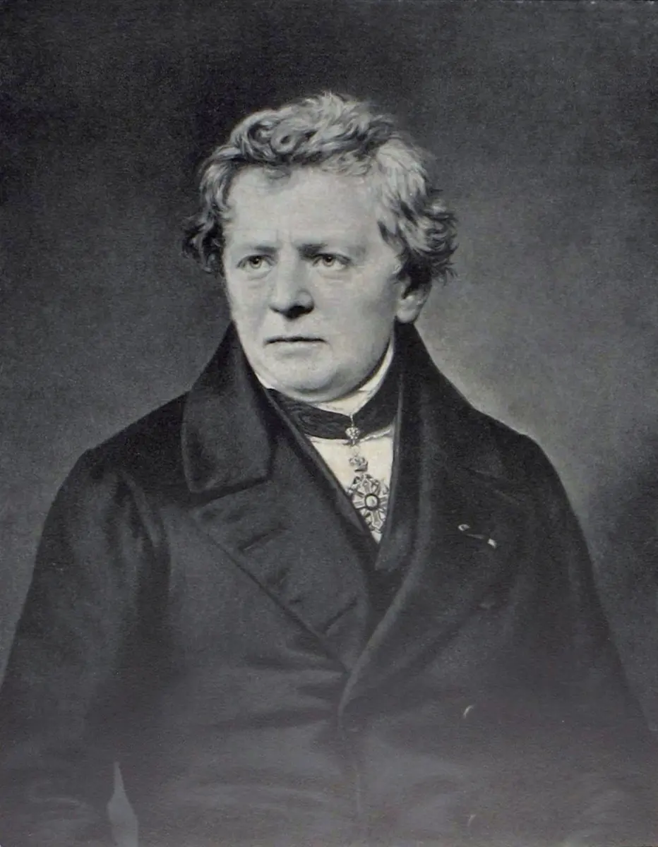
Every unit of resistance in the world carries the name of Georg Simon Ohm. His father was a locksmith, and his mother the daughter of a tailor; neither had been to school. His father taught himself, and then gave his sons an excellent education at home: Ohm’s brother Martin became a well-known mathematician. Ohm taught at a high school in Cologne, where, with wires he drew himself and a current-measuring needle he built, he found the relationship between the potential difference across a conductor and the current through it, now called Ohm’s law (1827). His work was received coldly at first; it was years before scientists accepted it, and he became a professor at Munich only near the end of his life.
23.1 Electric current
Electric current is the rate of flow of charge: the quantity of charge passing a given point each second.
where I is the current and ΔQ the charge that flows past the point in time Δt.
Current is measured in amperes (A), one of the seven SI base units. Since 2019 the ampere has been fixed by the charge of one electron: the elementary charge e is defined to be exactly 1.602 176 634 × 10⁻¹⁹ C, and one ampere is the current in which 1 / (1.602 176 634 × 10⁻¹⁹), about 6.24 × 10¹⁸, elementary charges pass a point each second. (Before 2019 the ampere was defined by the force between two parallel wires carrying it: 2 × 10⁻⁷ N on each meter of wire 1 m apart.)
In a laboratory, an ampere is quite a large current, so we often use the milliampere (1 mA = 10⁻³ A) and the microampere (1 µA = 10⁻⁶ A).
Rearranging the definition,
The charge that flows in a certain time is the current multiplied by the time. If a current of 1 A flows for 1 s, the charge that flows is one coulomb (C):
One coulomb is the charge that passes a point in one second when the current is one ampere: 1 C = 1 A s.
The coulomb is also a large amount of charge, so we often use µC or even nC. The charge on a single electron is only 1.6 × 10⁻¹⁹ C (in size).
A current of 2.0 mA flows for 5.0 minutes. The charge that passes is:
Pick an answer to see why.
23.2 Conventional current and drift velocity
Conventional current
“Conventional current” doesn’t mean the normal or usual current: a convention is an agreement. Long before the electron was discovered (by J. J. Thomson, in 1897), the scientists who worked on electricity agreed to say that current flows from the positive terminal of a supply, round the circuit, to the negative terminal.
In metal wires, the moving charges turned out to be electrons, which are negative, and drift the other way: from the negative terminal round to the positive. So conventional current is in the opposite direction to the flow of electrons. Nothing is wrong with this: a flow of negative charge one way has the same effect as a flow of positive charge the other way, and every rule in physics is written for conventional current.
Not every current is a flow of electrons. In a solution such as salt water or copper sulphate, or in an ionized gas such as the inside of a fluorescent tube, positive ions move in the direction of conventional current, and negative ions the other way.
The free electrons in a metal
Connect a battery, a switch and a lamp in series, and close the switch: the lamp lights, as far as we can tell, at once. How fast do the electrons move through the wires?
In a metal atom, the outermost electrons are held only loosely by the nucleus. In a solid metal they leave their atoms altogether and move freely among all the atoms (strictly, the positive ions the atoms have become). The metal ions sit in a regular lattice, like islands in a “sea” of free electrons, also called delocalized or conduction electrons. In most metals there is roughly one free electron per atom.
The free electrons are always moving, very fast, at speeds of about 10⁶ m/s (about a three-hundredth of the speed of light), in random directions, colliding with the ions all the time. Because the directions are random, this motion carries no charge along the wire overall. The free electrons are also why metals conduct heat so well.
Connect a cell across the wire, and the p.d. sets up an electric field along it. The field pushes every free electron away from the negative terminal and towards the positive terminal. Between collisions each electron gains a little velocity along the wire, so on top of its fast random motion it drifts slowly along. The average velocity of this drift is the mean drift velocity: it is tiny compared with the random speeds, but it is in one direction, so it carries the current.
The equation I = nAvq
Take a length d of wire of cross-sectional area A (Figure 23.4). It contains n free charge carriers per unit volume: n is the number density of the charge carriers, the number in each cubic meter (unit m⁻³).
The carriers in this length. The volume of the length is A × d, so the number of free carriers in it is n × A × d. Each carries a charge q (for an electron, the size of its charge, e), so the charge free to move in this length is
The time to pass the end. The carriers drift at the mean drift velocity v, so in a time
every one of them passes through the end face of the length.
The current. Current is charge per unit time:
and d cancels:
For electrons, q = e and I = nAve. The same equation holds for any charge carriers: ions in a solution or in a plasma (an ionized gas), where an ion may carry several times the electron’s charge (a Cu²⁺ ion carries 2e = 3.2 × 10⁻¹⁹ C).
Rearranged, : for a given current, the carriers drift faster in a thinner wire (smaller A) and in a material with fewer carriers (smaller n), such as a semiconductor.
The same current flows through a thick copper wire and a thin copper wire joined in series. In the thin wire, the drift velocity of the electrons is:
Pick an answer to see why.
23.3 Potential difference
Why do electrons flow round a circuit at all? A comparison with water flowing in pipes helps.
The water (Figure 23.6a). Water held high in a reservoir has gravitational potential energy. Open the tap, and the difference in water level (the height Δh) makes a pressure difference along the pipe: the water flows, and turns a paddle wheel on its way down to the sink. The water’s gravitational potential energy is turned into the kinetic energy of the turning wheel. If the wheel drove a pump, the water could be lifted back up from the sink to the reservoir, and go round again.
The circuit (Figure 23.6b). A chemical reaction in the cell makes an electrical potential difference (symbol V) between its terminals. When the switch is closed, the electric field this sets up pushes the electrons round the circuit and through the lamp. The chemical energy stored in the cell is turned into the vibrational kinetic energy of the atoms in the filament: its temperature rises, and it glows.
In every circuit, electrical energy is converted into other forms: a lamp turns it into thermal energy and light, an electric motor into mechanical energy, a loudspeaker into sound.
These energy conversions are the basis of the definition of potential difference:
The potential difference (p.d.) between two points in a circuit is the electrical energy converted into other forms (thermal, light, mechanical…) when unit charge passes from one point to the other.
or, since the energy converted is the work W done by the charge:
The unit of p.d. is therefore the joule per coulomb (J/C), called the volt (V):
A p.d. of 1 volt exists between two points in a circuit if 1 J of energy is converted when 1 C of charge passes between them: 1 V = 1 J/C.
Because p.d. is measured in volts, it is often called the voltage between two points.
23.4 Potential difference and electromotive force
Current only measures the rate at which charged particles flow round a circuit. It tells us nothing about the energy they carry. The quantity that describes the energy is the potential difference, symbol V, measured in volts.
The p.d. across a component is measured with a voltmeter connected across the component, in parallel with it. (An ammeter goes in series, so that the current being measured passes through it.)
Potential difference is the electrical work done by each coulomb of charge as it flows through a component such as a lamp, a motor or a resistor; the component turns that electrical energy into heat, light or other forms:
P.d. can’t describe what happens in a source of electrical energy: a cell, a generator or a mains power supply. These do the opposite: they transfer other forms of energy (chemical, kinetic, light in a solar cell) into electrical energy. For them we define a second quantity, the electromotive force (e.m.f.), symbol E:
The electromotive force of a source is the electrical work done on each coulomb of charge as it flows through the source (a cell, generator or power supply unit): the energy converted into electrical energy per unit charge.
Both e.m.f. and p.d. are measured in volts, with a voltmeter. Despite its name, e.m.f. is not a force: it is energy per charge.
Conservation of energy, round a loop. In a series circuit, the energy each coulomb gains in the sources must all be given up in the components by the time it gets back round. So, round any complete loop:
A 6 V battery driving a lamp and a resistor in series might give 4 V across the lamp and 2 V across the resistor: 4 + 2 = 6.
A cell of e.m.f. 1.5 V drives a charge of 20 C round a circuit. The energy it converts into electrical energy is:
Pick an answer to see why.
23.5 Resistance
When current flows through a material, the material gets in the way of the flow. On a microscopic level, the drifting electrons collide with the vibrating positive ion cores of the metal lattice. In each collision the electron gives up some of the energy it gained from the field, and the ions vibrate more: the wire heats up. This is why a current always heats a wire (except a superconductor).
Resistance is the opposition of a component to the flow of electric current through it. Its symbol is R and its unit is the ohm (Ω).
The same picture explains why the resistance of a metal increases as its temperature rises. In a hotter metal the ion cores vibrate with larger amplitude and get in the way of the drifting “gas” of electrons more often.
Components with a very high resistance let almost no current through them: they are insulators. And some materials, cooled to very low temperatures, have zero resistance: they are superconductors. A current set going in a superconducting loop keeps flowing for years with no cell at all. The magnets of MRI scanners in hospitals are superconducting coils, cooled by liquid helium to about −269 °C.
23.6 Current–potential difference characteristics and Ohm’s law
Many properties of a component can be found from a graph of the current through it against the p.d. across it. This graph is called the component’s electrical characteristic, or its I–V characteristic. It is measured for both directions of current, which some books call forward and reverse bias, by connecting the component one way round and then the other: negative values of V and I mean the current is the other way.
The simplest characteristic is that of a fixed resistor: a straight line through the origin. The graph can be drawn with either variable on either axis.
23.6.1 Ohm’s law
In 1827, Georg Ohm measured the current through metal wires at different p.d.s, keeping the temperature constant. He found that the current I through a wire was directly proportional to the p.d. V across it, as long as the temperature (and other physical conditions) stayed the same: the characteristic is a straight line through the origin.
Ohm’s law: the current through a metal conductor is directly proportional to the potential difference across it, provided its temperature and other physical conditions remain constant.
Ohm’s law holds only for some conductors, and only in some conditions: it is a special case, true of metal wires at constant temperature. The idea of resistance, however, applies to every component. The resistance of a component is defined as the ratio of the p.d. across it to the current through it:
The ohm: a component has a resistance of one ohm if a p.d. of 1 V across it drives a current of 1 A through it: 1 Ω = 1 V/A.
This definition holds for every component, whether it obeys Ohm’s law or not, at each point of its characteristic. It says that for a given p.d., a small current means a large resistance; and that for a given current, a large resistance needs a large p.d. to drive it. What Ohm’s law adds is that, for an ohmic conductor, R is the same at every point.
If the characteristic is drawn with current on the x-axis and p.d. on the y-axis (a V–I graph), then for a component that obeys Ohm’s law the gradient of the line is the resistance. A high resistance gives a steep line; a low resistance, a shallow one. (On an I–V graph, the gradient is 1/R, so a high resistance gives a shallow line: always check which way round the axes are.)
Fixed resistors and metal wires at constant temperature obey Ohm’s law over their whole range of current: their characteristics are straight lines through the origin. They are called ohmic conductors.
On a graph of p.d. (y-axis) against current (x-axis), the line for resistor X is steeper than the line for resistor Y. Then:
Pick an answer to see why.
23.6.2 Other electrical characteristics
The filament lamp. A tungsten filament lamp turns electrical energy into light and heat. As the current increases, the electrons collide with the tungsten ions more often and give them more energy: the ions vibrate with larger amplitude, the temperature rises (to over 2000 °C), and so does the resistance. A higher current means a higher temperature, which means a higher resistance. The characteristic bends: as V increases, the ratio V/I, the resistance, increases.
Components whose characteristics are not straight lines through the origin are non-ohmic conductors. Their resistance V/I depends on the current.
Fixed resistors and filament lamps behave the same with the current in either direction: their characteristics have the same shape for positive and negative p.d.
The semiconductor diode doesn’t. Diodes act as one-way valves for current: they let it flow in one direction and block it in the other. They are found in nearly every electronic circuit, and in mains power supplies (chargers and adapters) they turn alternating current (a.c.) into direct current (d.c.).
A diode conducts only in forward bias, in the direction the arrow of its symbol points. On the component itself, a colored ring marks the end the current comes out of (the end with the bar in the symbol). In reverse bias it doesn’t conduct: its resistance is very high (effectively infinite). In forward bias it hardly conducts at all until the p.d. reaches about 0.6 V (for silicon); after that, its resistance becomes very low and the current rises steeply. The characteristic of a diode is usually drawn as current (y-axis) against p.d. (x-axis):
A component’s resistance V/I rises as the current through it increases. It could be:
Pick an answer to see why.
23.6.3 Thermistors
A thermistor (from thermal resistor) is a component whose resistance changes a lot with temperature. It is made from the oxides of metals, in many shapes and sizes, so that its resistance changes much more than an ordinary resistor’s.
Most thermistors are negative temperature coefficient (NTC) thermistors: their resistance decreases as their temperature increases. (In a semiconductor, more charge carriers are freed as it warms, which outweighs the extra vibration of the lattice.) The change is non-linear: a graph of resistance against temperature is a curve.
The resistance changes by a large amount with temperature, but the change is non-linear: the curve is steep at low temperatures and flattens as the temperature rises.
Thermistors are used to sense temperature and to control devices: the change in the thermistor’s resistance changes a current or a voltage in a circuit, which can switch something on or off. They are found in:
- thermal cut-outs that switch a device off before it overheats (a hair dryer, a phone’s battery charger);
- room heaters, water heaters, rice cookers and refrigerators that hold a temperature;
- digital thermometers, including the ones used to check a fever;
- car engines’ management circuits.
23.6.4 Strain gauge
A strain gauge is a length of very fine wire, folded back and forth many times, sealed in a small rectangle of thin plastic. It is glued very firmly to the material under test: a beam of a bridge, the wing of an aircraft, the deck of a weighing scale.
When the material is stretched (it experiences a strain), the gauge and its wire are stretched too. The wire gets slightly longer and its cross-sectional area slightly smaller: both changes increase its resistance. The folded strands make the total length of wire large, so a small strain gives a measurable change.
How large is the change? The resistance of a wire of length L and uniform cross-sectional area A is (Section 23.7)
where ρ is the resistivity of the wire’s material. When the wire extends by a small amount ΔL, take the change in its area as negligible. The new resistance is
Subtracting the first equation from the second:
The strain is proportional to the extension ΔL, so the change in resistance is proportional to the strain. Measuring ΔR measures how much the material has stretched. (In a real gauge the area does shrink a little, which adds to the change; the result is still proportional to the strain.)
23.6.5 Light-dependent resistor (LDR)
A light-dependent resistor (LDR) is made by laying a film of a semiconductor, such as cadmium sulphide, between two metal electrodes. Light falling on the semiconductor frees electrons in it, which can then carry current: the brighter the light, the lower the resistance. Typically, its resistance is about 1 MΩ in moonlight and about 100 Ω in sunlight.
At a steady light intensity the resistance of an LDR is constant, but it changes with the intensity, and not linearly: a graph of resistance against light intensity is a curve, falling steeply in dim light and flattening in bright light (Figure 23.35, in the exercise).
23.6.6 The temperature characteristic of an NTC thermistor
The resistance of most materials changes slightly with temperature. A thermistor is made so that the change is large (Figure 23.15). For an NTC thermistor, as the temperature θ rises, the resistance R falls: by a large amount, but not in a straight line.
23.7 Resistivity
How do we compare how well different materials conduct? How do we choose a material for the pins inside a mains plug, or for the insulators that hold up a high-voltage line? The resistance of a wire depends on its length and its cross-sectional area, as well as on the material it is made of.
- Length. The resistance R increases with the length l: there are more ion cores in the way of the electrons. If the length doubles, the resistance doubles: .
- Area. The resistance decreases as the cross-sectional area A increases: there are more pathways side by side for the electrons. If the area doubles, the resistance halves: .
Combining both proportionalities:
Replacing the proportionality sign by a constant of proportionality ρ:
ρ (the Greek letter rho) is the resistivity of the material. It gives the resistance of the material itself, whatever the size and shape of the piece. Rearranged, it defines resistivity:
with R in ohms, A in square meters and l in meters, so the unit of resistivity is the ohm meter (Ω m).
The resistivity of a material is numerically the resistance of a piece of it 1 m long with a cross-sectional area of 1 m² (a 1 m cube, with the current between opposite faces).
The resistivity of a material depends on its inside: in particular, on the number of free charge carriers per cubic meter and on how easily they move through the structure (their mobility). The arrangement of the atoms, any impurities, and the temperature all affect the mobility.
| Material | Resistivity at 20 °C (Ω m) | |
|---|---|---|
| silver | 1.6 × 10⁻⁸ | best conductor |
| copper | 1.68 × 10⁻⁸ | wires and cables |
| aluminium | 2.7 × 10⁻⁸ | overhead power lines |
| tungsten | 5.6 × 10⁻⁸ | lamp filaments |
| nichrome | about 1.1 × 10⁻⁶ | heater elements |
| carbon (graphite) | about 3 × 10⁻⁵ | resistors |
| silicon (pure) | about 2 × 10³ | semiconductor |
| glass | about 10¹⁰–10¹⁴ | insulators |
| ABS plastic | about 1 × 10¹⁵ | mains plugs |
Good conductors have very low resistivities; good insulators, such as ABS plastic (the material most mains plugs are made of), have extremely high ones: there is a factor of about 10²³ between copper and ABS. Superconductors have zero resistivity below a certain critical temperature.
A water picture. A hose pipe packed with sand is like a material of high resistivity: push water through it, and only a trickle comes out. An empty hose pipe, under the same pressure, lets the water rush through: a low resistivity. But how much flows also depends on the hose’s length and width, just as a wire’s resistance depends on its length and area as well as its resistivity.
Resistivity and temperature.
- The resistivity of metals increases with temperature (the ions vibrate more).
- The resistivity of many semiconductors, such as silicon and germanium, decreases as they warm: more charge carriers are freed, which outweighs the extra vibration. NTC thermistors work this way.
- A superconductor behaves like a metal above its critical temperature, its resistivity falling as it cools; at the critical temperature its resistivity drops suddenly to zero.
A wire is stretched to twice its length, its volume staying the same. Its resistance becomes:
Pick an answer to see why.
23.8 Resistors in series
Resistors are in series when they are joined one after another with no junction between them, so that the same current flows through all of them. Let I be the common current.
The p.d.s add. By conservation of energy, the energy each coulomb gives up in R₁ and in R₂ adds up to the energy it gives up across the pair:
Each p.d. By V = IR,
The single resistor. One resistor R that would carry the same current I at the same p.d. V has V = IR. So
For more than two resistors in series, simply add all of them: Adding resistors in series increases the total resistance.
23.9 Resistors in parallel
In a parallel circuit, the current splits: each resistor is connected across the same two points, so each has the same p.d. V across it.
The currents add. By conservation of charge, the current flowing into a junction equals the current flowing out:
Each current. By Ohm’s law, , , and for the single equivalent resistor . So
Dividing by V:
For two resistors this gives (product over sum). The formula shows that the total resistance of resistors in parallel is smaller than the smallest of them: each new branch is a new path for the current.
With these two rules, any group of resistors connected in series or in parallel can be replaced by a single resistor, which greatly simplifies a circuit.
A 6 Ω and a 3 Ω resistor are joined in parallel. Their combined resistance is:
Pick an answer to see why.
23.10 Potential dividers
A potential divider uses two resistances in series to divide an input p.d. into smaller parts. It can give a fixed or a varying output p.d., which becomes the input to another circuit, or be used to measure a p.d. or a resistance. The volume knob of a radio is a potential divider.
23.10.1 The potential divider circuit
In the circuit of Figure 23.23, the voltmeter has a very high resistance, so the tiny current through it can be ignored. Then:
- R₁ and R₂ are in series, so the total resistance is , and the same current I passes through both;
- the p.d.s across them add up to the input: .
By V = IR, and . Dividing V₁ by V₂:
The p.d. is divided in the ratio of the resistances: the larger resistance takes the larger share.
And since ,
23.10.2 Potential dividers as sensors
The most useful potential dividers are sensor circuits. Replace R₂ by a component whose resistance changes with a physical quantity, such as temperature or light intensity, and the p.d. across the fixed resistor R₁ changes with that quantity too. The voltmeter across R₁ can then be calibrated in degrees or in lux: the circuit becomes an electronic thermometer or an electronic light meter, or its output can switch a heater, a fan or a lamp on and off.
An electronic thermometer. With an NTC thermistor as R₂: as the temperature rises, the thermistor’s resistance falls, so it takes a smaller share of the p.d., and the p.d. V₁ across the fixed resistor rises. Increasing temperature gives an increasing output. If the voltmeter were connected across the thermistor instead, the opposite would happen: the output would fall as the temperature rises. Most uses want the output to rise with temperature, so the voltmeter is usually connected across the fixed resistor.
A light sensor. An LDR is made of a semiconductor: as light shines on it, electrons are freed and can carry current, so its resistance falls. In the dark an LDR’s resistance can be of the order of megohms, while in bright light it can drop to a few hundred ohms. With an LDR as R₂, as the light gets brighter, the output V₁ across the fixed resistor rises.
A street light that switches on at dusk uses the opposite arrangement: with the fixed resistor and the LDR swapped (or the output taken across the LDR), the output rises as it gets darker, and switches the lamp on when it passes a set value.
In a potential divider of a fixed resistor and an NTC thermistor across a 9 V battery, the output is taken across the thermistor. As the thermistor is warmed, the output:
Pick an answer to see why.
23.11 Internal resistance and electromotive force
Measure the p.d. across the terminals of a cell, its terminal p.d., and it depends on the current being drawn from it. When no current is drawn (the cell on open circuit), the terminal p.d. has its largest value: this is the cell’s e.m.f. As the current increases, the terminal p.d. falls. Why?
The chemicals inside a cell oppose the flow of current through it: the cell has an internal resistance, r. When the cell drives a current through an external circuit (a load), part of its e.m.f. drives the current through the load, and the rest drives the same current through its own internal resistance. The internal resistance behaves as if it were a resistor in series with an ideal cell and the external circuit.
The chemical action inside a cell produces a surplus of electrons at one terminal (the negative) and a shortage at the other (the positive). It can keep electrons flowing, a current, through any circuit connected across its terminals, for as long as the chemical action lasts. The cell does work in moving charge round the circuit:
Electromotive force (e.m.f.), symbol E, is the electrical work done by a source in moving unit charge round a complete circuit:
In a circuit, the current carries energy from a store, such as a battery, to the components, which pass it on to the surroundings: a lamp, for example, by light and by heating.
Real power supplies, batteries and laboratory power packs, always have some internal resistance r. As the current flows through the supply, its internal resistance has a p.d. across it, and some electrical energy is turned into thermal energy inside the supply. That is one reason a phone or tablet warms up when it is used, or charged, for a long time.
The internal resistance of most batteries and power supplies is very low: a typical AA cell has an internal resistance of about 0.2 Ω, so it can usually be ignored in a circuit of several ohms. It matters when the external resistance is small, or the current large: a car’s starter motor draws over 100 A, and its battery must have an internal resistance of only a few milliohms.
Finding E and r
The internal resistance can’t be measured directly: it is “inside” the supply. It is found from the supply’s characteristic, with a circuit like Figure 23.26.
By conservation of energy, the e.m.f. equals the sum of the p.d.s round the circuit. There are two: the p.d. V across the external variable resistor (the terminal p.d., which the voltmeter reads) and the p.d. across the internal resistance, which can’t be measured directly but is equal to Ir. So:
The current I is measured by the ammeter, and E and r are constants, so this can be rewritten as
which is the equation of a straight line, y = mx + c, with a negative gradient. Plot the terminal p.d. V against the current I, for different values of the load resistance R:
- the intercept on the V-axis (where I = 0) is the e.m.f. E;
- the gradient is −r: its magnitude is the internal resistance.
The difference E − V = Ir is sometimes called the lost volts: the p.d. used up inside the cell.
Putting V = IR for the external resistor into E = V + Ir gives another useful form, which finds the current:
A cell of e.m.f. 2.0 V and internal resistance 0.50 Ω drives a current of 1.0 A. Its terminal p.d. is:
Pick an answer to see why.
23.12 Energy and power in electrical circuits
Consider a simple circuit in which a steady current I flows through a load: a motor, a heater, or simply a resistor. As the charge flows through the load, it loses potential energy, which the load turns into other forms (it dissipates the energy). The energy dissipated equals the potential energy lost by the charge as it moves through the p.d. between the load’s input and output terminals.
From the definition of p.d., the energy dissipated is
where W is the energy dissipated in a time t, Q is the charge that flows in time t, and V is the p.d. across the load. The current is steady, so Q = It, and therefore
Power is the rate of dissipation (or transfer) of energy, . Since V and I are constant:
For a resistor, V = IR, so two more forms follow:
The unit of power is the watt (W): 1 W = 1 J/s. W comes out in joules and P in watts when V, I and t are in volts, amperes and seconds. (Don’t confuse W for energy, in the equations, with W for watts, the unit.)
Which form to use? when the current is known (resistors in series share a current, so the larger resistance gets the larger power); when the p.d. is known (resistors in parallel share a p.d., so the smaller resistance gets the larger power).
Exercise
Choose the correct option
- Four resistors of resistances 1.0 Ω, 2.0 Ω, 3.0 Ω and 4.0 Ω are connected together as shown in the figure above. A battery is connected across the 1.0 Ω resistor. If I₀ is the battery current and I₁ is the current in the 4.0 Ω resistor, the ratio is:
Pick an answer to see why.
- Four different types of lamps produce the same brightness. The power consumption and the current marked on the packaging of each are shown in the table. Which type of lamp has the greatest efficiency?
| Type of lamp | Power (W) | Current (A) |
|---|---|---|
| filament | 60 | 0.25 |
| fluorescent | 12 | 0.05 |
| halogen | 48 | 4 |
| LED | 6 | 0.5 |
Pick an answer to see why.
- In the circuit above, the battery converts an amount E of chemical energy to electrical energy when a charge Q passes through the resistor in time t. Which expressions give the e.m.f. of the battery and the current in the resistor?
Pick an answer to see why.
- A lightning strike takes a time t. During the strike, electrons are discharged to the Earth, making a current I. An expression for the total number of electrons discharged to the Earth is:
Pick an answer to see why.
- The combined resistance R of two resistors R₁ and R₂ in parallel is given by . Which statement is used in the derivation of this formula?
Pick an answer to see why.
- A cell of e.m.f. ε and internal resistance r is connected to a resistor of resistance R. The current in the circuit is I. An expression for the terminal potential difference V across the cell is:
Pick an answer to see why.
- A motor is used to lift a mass m through a height h in a time t. It draws a current I from the power supply, and the p.d. across the motor is V. A correct expression for the efficiency of the system is:
Pick an answer to see why.
- A student investigates the e.m.f. ε and internal resistance r of a cell. The p.d. V across the cell and the current I in it are measured as the load resistance is increased, and plotted on the graph above. How are ε and r found from the graph?
Pick an answer to see why.
- A battery with internal resistance is connected to a fixed resistor, an ammeter and a voltmeter, as shown above. The battery is replaced by one with the same e.m.f. but a greater internal resistance. What happens to the readings on the ammeter and the voltmeter?
Pick an answer to see why.
- When four identical lamps P, Q, R and S are connected as shown in diagram 1, they have normal brightness. When they are connected as shown in diagram 2, which statement is correct?
Pick an answer to see why.
- A nichrome wire is 1 m long and 1 × 10⁻⁶ m² in cross-sectional area. When it is connected to a p.d. of 2 V, a current of 4 A flows in it. The resistivity of this nichrome is:
Pick an answer to see why.
Numerical problems
- a.The copper wire supplying the sockets in your house has a cross-sectional area of 2.5 mm². A hair dryer draws a current of 8.2 A. What is the mean drift velocity of the electrons in the wire? Take the number density of free electrons in copper as 8.49 × 10²⁸ m⁻³.
- b.A 1 molar solution of copper sulphate contains 6.02 × 10²⁶ Cu²⁺ ions per cubic meter. A beaker of this solution has two electrodes placed in it, through which a current of 30 mA is passed. What is the mean drift velocity of the copper ions? Take the cross-sectional area of the solution as 100 cm², and assume the copper ions carry all the current.
Hint
Answer
A tungsten lamp filament of diameter 0.046 mm carries a current of 0.50 A. What is the mean drift velocity of the electrons in the filament? Take the number density of free electrons in tungsten as 1.26 × 10²⁹ m⁻³.
Answer
A copper wire of diameter 0.65 mm carries a current of 0.25 A. There are 8.5 × 10²⁸ charge carriers in each cubic meter of copper; the charge on each carrier (an electron) is 1.6 × 10⁻¹⁹ C. Calculate the drift speed of the charge carriers.
Answer
- a.State what physical quantity is represented by each term in the equation I = nAvq.
- b.A semiconducting strip 6.0 mm wide and 0.50 mm thick carries a current of 10 mA along its length, as shown. If the value of n for the semiconducting material is 7.0 × 10²² m⁻³, show that the drift speed of the charge carriers, each of charge 1.6 × 10⁻¹⁹ C, is about 0.3 m/s.
Answer
The resistance of a light-dependent resistor (LDR) as a function of light intensity is shown in the graph below.
A manufacturer of light-sensitive switches wants to use this LDR to turn a set of garden lights on when the outdoor light intensity drops below 200 lux. Draw a potential divider that would let the garden lights’ circuit switch the lights on when its output p.d. falls to 2.5 V or below.
Hint
Answer
The figure below shows a circuit diagram. The current measured by the ammeter is 220 mA.
- a.Calculate the value of the resistance R.
- b.Describe how the total current in the circuit would change if the resistor R were disconnected from the circuit. Explain why the current would change in that way.
The textbook draws the two cells facing opposite ways. That gives 10.5 − 6 = 4.5 V and a total resistance of 4.5 ÷ 0.22 = 20.5 Ω, less than the 21.2 Ω of the resistors that are plainly in series, so R would have to be negative. So the book’s numbers don’t work; here the cells face the same way (16.5 V).
Hint
Answer
Printable PDFs
- The unit as a book (A5) 27 pages Answers as an A4 booklet, 7 sheets
- Study notes 3 pages
- Worksheet 5 pages Answer key
- Harder practice questions 2 pages Answer key
Quiz yourself: Electricity and Magnetism, Grades 5–12 →
Practice every question in the book, and keep track of the ones you miss →
A companion to your textbook, not a replacement for it: study from the book your school uses, and where the two differ, follow your teacher. Found a mistake? Please tell us.