
Walk up almost any hill in Nepal and you will hear a stream before you see it. Beside many of them stands a little stone hut, the ghatta, where the stream has been grinding maize and millet for longer than anyone can remember. Water from a wooden chute strikes a small wheel under the floor, and the wheel turns the millstone above it, all day and all night, for nothing.
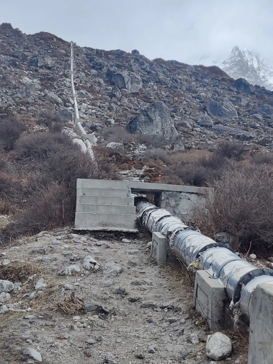
In thousands of hill villages the same streams now light the houses too. A small pipe takes some of the water down the hillside to a shed, where it spins a turbine and a generator, and at dusk the lights come on in every house, with no power line from the national grid for miles around.
You learned in Grade 9 how a big hydropower station works Grade 9: Hydroelectricity, and in Grade 10 how a generator makes electricity Grade 10: Dynamo and a.c. generator. This topic asks the question an engineer asks first: how much electricity can this stream make? You will measure a stream’s drop and flow, work out its power, follow the energy from the water to the wire, and then build a small turbine of your own, test it, and make it better.
Power: energy every second
In Grade 9 you met power, the energy changed from one form to another in each second, measured in watts: 1 W = 1 J/s Grade 9: Electric power. A 10 W LED bulb turns 10 joules of electrical energy into light and heat every second.
A stream’s power comes from water losing height. When a mass m of water falls a height h, it loses gravitational potential energy mgh (Gravitational potential energy). A hydropower plant catches part of that energy before the water reaches the bottom. What matters is how much energy is released every second, and that depends on two things you can measure:
- The head (H): the height the water falls, in meters, from the water’s surface where it is taken in to the turbine.
- The flow (Q): how much water passes each second, in liters per second (L/s) or cubic meters per second (m³/s; 1 m³/s = 1,000 L/s). One liter of water has a mass of 1 kg.
If Q liters pass each second, then Q kilograms of water fall the height H each second, and the energy they release each second is QgH. So the power in the water is
with Q in kg/s (the same number as L/s), g = 9.8 m/s² and H in meters, giving watts. A quick way to remember it: one liter a second, falling one meter, gives about 10 W.
An engineer finds a way to double the head of a scheme, by taking the water in higher up the stream, and the flow stays the same. The power in the water
Pick an answer to see why.
From water to wire
No plant turns all of the water’s power into electricity. You met efficiency in Grade 9: the useful energy out ÷ the energy put in, always less than 100% Grade 9: Efficiency. Follow the energy of a small hydropower plant from the stream to a village house, and at every step some of it is lost, mostly as heat:
| Step | What is lost | Fraction passed on (rough values for a small plant) |
|---|---|---|
| the pipe (penstock) | friction between the water and the pipe’s wall | 0.90 |
| the turbine | splashing, swirling water, water leaving with speed it still has | 0.70 |
| the belt from turbine to generator | friction and bending of the belt | 0.95 |
| the generator | heating of its coils and core, friction in its bearings | 0.85 |
Each step passes on a fraction of what it gets, so the overall efficiency is the fractions multiplied together:
About half. Designers of small plants often plan on an overall efficiency of about 50% (some guides allow 60% or more for a well-built plant), and a small turbine on its own typically turns about 65% to 80% of the power it receives into work, depending on its kind and how well it is made. So the electrical power of a small plant is roughly
where η (eta) is the overall efficiency. And the line that carries the electricity to the houses loses some more.
A small plant has 20 kW of power in its water and gives 9 kW of electricity. Where did most of the other 11 kW go?
Pick an answer to see why.
Measuring a real stream
To know how much a stream can give, you need its head and its flow. Neither needs special instruments.
Measuring the head
The head is the height from the water’s surface in the forebay to the turbine. On a steep hillside you can measure it with a long, clear plastic hose full of water, because water in a hose always settles at the same level at both ends, however the hose runs between them. One person holds one end with its water level at a mark on the ground; a second person, further down, holds the other end against a measuring stick and raises it until the water stops moving. The height of the water up the stick is the drop between the two places. Then the first person moves down to the second one’s place, and you do it again, step by step, down the hill. The head is the sum of the steps.
A phone’s GPS height isn’t good enough for this: it is often wrong by several meters or more, as much as a whole small head.
Measuring the flow
For a very small stream, catch all of it in a bucket and time how long it takes to fill: a 15 L bucket that fills in 5 s means a flow of 15 ÷ 5 = 3 L/s.
For a bigger stream, use the float method. Choose a straight stretch where the water flows smoothly. Mark a start and a finish 10 m apart, drop a float (a small stick or an orange) into the middle above the start, and time it to the finish. That gives the speed of the water at the surface. Water near the bed and the banks is slowed by friction, so the average speed is less: about 0.8 to 0.9 times the surface speed, nearer 0.8 for a rough, rocky bed. Measure the depth at evenly spaced points across, to get the area of the stream’s cross-section: each depth stands for a strip of the stream as wide as the spacing, so the area is about the spacing × the sum of the depths. Then
When to measure, and how much to take
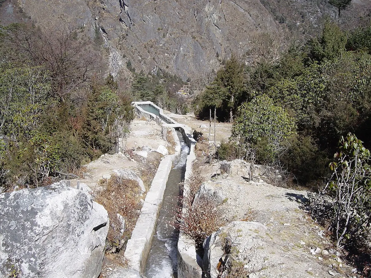
Most small schemes in Nepal are run-of-river: they have no reservoir, and use the water as it comes. A stream that roars in the monsoon may be a trickle in the dry months before it, so engineers measure the flow in the dry season and design for that, or the lights go dim every spring.
A scheme also must not take the whole stream. Fish, the fields and the ghattas below need water too. Nepal’s Hydropower Development Policy (2001) asks every hydropower project to leave at least 10% of the river’s lowest monthly average flow in the river, or more where a study of the river’s life says it needs more. The water that has passed through the turbine goes back into the stream, so the only stretch that runs low is between the weir and the powerhouse.
In the float method, why is the average speed of the water taken as less than the speed of the float?
Pick an answer to see why.
Turbines: catching the energy
A turbine is a wheel that the water turns. Its job is to take as much as possible of the water’s energy, and leave the water with as little as possible.
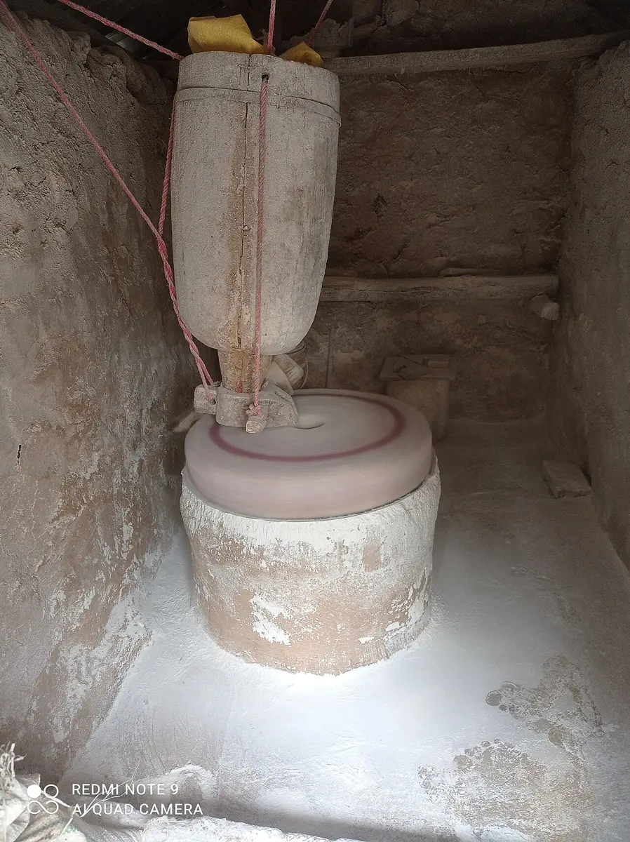
The ghatta’s wheel is one of the oldest turbines: a ring of flat wooden paddles on an upright shaft, turned by a jet of water from the chute, with the millstone fixed to the top of the same shaft. It is simple and cheap, but it wastes most of the water’s power. Can a better wheel catch more?
Turning the head into speed
Most small turbines in Nepal first turn the head into speed. The water is sent down the penstock and out of a narrow nozzle at the bottom as a fast jet. Its gravitational potential energy has become kinetic energy, just as for a falling ball (Swapping one for the other), so if nothing were lost
The best speed for the wheel
Now the jet hits the cups around the rim of a wheel. How fast should the wheel turn?
- If the wheel is held still, the jet pushes hard, but nothing moves, so no work is done: no power.
- If the cups move as fast as the jet, the water can’t catch up with them: no push, so again no power.
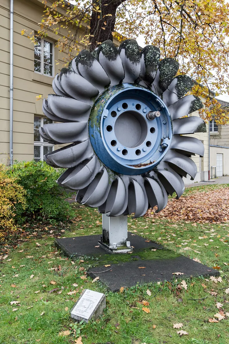
The best is in between. If the water simply pushes a flat paddle aside, the most a paddle can take is half the jet’s energy, when the paddle moves at half the jet’s speed: the water flies off sideways, still carrying the other half. But if the cup is shaped to turn the water right round and send it back the way it came, at half the jet’s speed backwards relative to a cup moving forwards at half the jet’s speed, the water ends up almost at rest. It has given the cup nearly all its kinetic energy.
Different heads, different turbines
A Pelton wheel needs a fast jet, so it suits a big head. With a low head, the jet would be slow, and the wheel would turn too slowly to drive a generator. Other turbines take the water differently.
A rough guide that micro-hydro engineers use:
| Head | Turbines that suit it |
|---|---|
| high (over about 50 m) | Pelton, Turgo (a cousin of the Pelton) |
| medium (about 10 to 50 m) | crossflow, Pelton with several jets, Turgo, Francis |
| low (under about 10 m) | crossflow, propeller, Kaplan (a propeller whose blades can turn) |
In Nepal the Pelton and the crossflow turbine are the most common in small plants, and most of them are made in Nepal’s own workshops. The crossflow suits a wide range of heads and flows, and it is simple to make from steel plate and pipe. For the smallest plants there is the peltric set: a small Pelton wheel on the same shaft as an ordinary electric motor, which works as a generator when it is turned. According to the Alternative Energy Promotion Centre (AEPC), peltric sets made in Nepal give up to 5 kW.
A village has a stream with a big flow but a drop of only 3 m near the village. Which turbine is the best choice?
Pick an answer to see why.
From turbine to generator
The turbine turns a generator, which you met in Grade 10: a coil turning in a magnetic field Grade 10: The a.c. generator. Two things make a small plant’s generator harder to run than the bicycle dynamo.
The speed must be right. Mains electricity in Nepal goes through 50 complete cycles a second (50 Hz), and lights and machines are made for that. A common generator has four magnetic poles and gives one complete cycle for every half turn, so it must turn 25 times a second, 1,500 times a minute. Most turbines turn more slowly, so a belt from a big pulley on the turbine to a small one on the generator speeds it up (a wheel and axle at work).
The speed must stay the same. At dusk, the villagers switch their lights on all at once. The generator then has more load, the turbine slows down, and the voltage and frequency drop; switch them off, and it races. A big station opens and closes a valve. A small plant uses something simpler: an electronic load controller, which keeps the total load the same. Whatever power the village isn’t using, it sends to a ballast, often a heater in a tank of water. Switch on 100 W of lights, and the controller sends 100 W less to the ballast. The turbine never notices.
Design, build, test, improve
Engineers don’t only work out a design on paper. They build it, test it by measuring how well it works, and improve it, again and again. Every design must meet some criteria (what it must do: give 6 kW, say) within some constraints (what it mustn’t break: cost, the materials to hand, the water that must be left in the stream).
Now try it yourself, on a small scale. Your wheel won’t make electricity (unless you have a small motor from an old toy, which works as a generator when it is turned), but you can measure its output another way: by the weight it lifts. The energy you put in is the potential energy of the water you pour through it; the energy you get out is the potential energy of the load it lifts.
Small hydropower in Nepal
The Alternative Energy Promotion Centre (AEPC), the government’s agency for renewable energy, sorts small hydropower plants by their electrical power:
| Kind | Power |
|---|---|
| pico hydro | up to 10 kW |
| micro hydro | over 10 kW, up to 100 kW |
| mini hydro | 100 kW to 1 MW |
As of July 2025, plants built with AEPC’s support give 40,655 kW together, about 41 MW, and 11,104 improved water mills have been installed with its support: ghattas given metal wheels in place of wooden ones (AEPC’s figures at its 29th anniversary, November 2025). An improved mill can grind faster than the old ghatta, and drive a small generator as well, giving up to 3 to 5 kW. There are still thought to be about 25,000 traditional ghattas in Nepal, perhaps more.
41 MW is small next to Nepal’s big stations: Upper Tamakoshi alone, at 456 MW, gives about eleven times as much Grade 10: Electricity in Nepal. But a micro-hydro plant reaches villages days’ walk from the nearest power line, where a big station’s electricity never could, and it is built, run and repaired by the village itself.
Questions
A plant has a head of 25 m and a flow of 40 L/s. What power is in its water?
Pick an answer to see why.
A Pelton wheel’s cups move at the same speed as the jet. How much power does the wheel give?
Pick an answer to see why.
A stream gives 120 L/s down a head of 15 m. a. What is the power in the water? b. If the overall efficiency is 55%, what electrical power will the plant give? c. Is this a pico, micro or mini hydro plant, by AEPC’s classes?
Answer
- a.P = QgH = 120 × 9.8 × 15 = 17,640 W, about 17.6 kW.
- b.0.55 × 17,640 = 9,702 W, about 9.7 kW.
- c.Under 10 kW, so a pico hydro plant, only just.
A small plant’s penstock passes on 92% of the water’s power, its turbine 75%, its belt drive 96% and its generator 88%. a. What is the overall efficiency? b. The engineers can afford to improve one part: a better turbine at 82%, or a better generator at 92%. Which improves the plant more? Show your working.
Answer
- a.0.92 × 0.75 × 0.96 × 0.88 = 0.58, about 58%.
- b.With the better turbine: 0.92 × 0.82 × 0.96 × 0.88 = 0.637, about 64%. With the better generator: 0.92 × 0.75 × 0.96 × 0.92 = 0.609, about 61%. The turbine improves it more, because it was the part losing the most. (Engineers improve the weakest part first.)
Explain why the float method gives a flow that is too big unless you multiply the float’s speed by a number less than 1.
Answer
The float moves with the water at the surface in the middle of the stream, which is the fastest-moving water. Near the bed and the banks, friction slows the water down. The flow is the area of the cross-section × the average speed of all the water in it, which is less than the surface speed in the middle, about 0.8 to 0.9 times it. Using the float’s speed alone would give a flow 10 to 25% too big.
A team tests three designs of a home-made water wheel. Each time they pour 2.0 kg of water through a drop of 0.50 m, and measure how high it lifts a 40 g load. (These results are made up.)
| Design | Lift |
|---|---|
| A: 6 flat blades | 0.20 m |
| B: 6 spoon cups | 0.45 m |
| C: 10 spoon cups | 0.40 m |
a. Work out the input energy and each design’s efficiency. b. Which design is best, and what might explain the result for C? c. Suggest the next change the team should test, and how to make the test fair.
Answer
- a.Input = mgh = 2.0 × 9.8 × 0.50 = 9.8 J. Output = 0.040 × 9.8 × lift: A, 0.040 × 9.8 × 0.20 = 0.078 J, efficiency 0.078 ÷ 9.8 = 0.8%; B, 0.176 J, 1.8%; C, 0.157 J, 1.6%.
- b.B. Cups turn the water back and take more of its energy than flat blades. With 10 cups (C), they are crowded: one cup may shield the next from the jet, or water from one cup may splash onto the back of the next, pushing it the wrong way; the extra weight may add friction too.
- c.For example: a narrower jet aimed at the middle of the cups, or a lighter or heavier load to find the best load, or smoother bearings. Change only that one thing; keep the water, the drop, the load (unless the load is what is being tested) and the way of measuring the same; and repeat each test two or three times and take the average.
A village has two possible sites for its plant. Site 1: a head of 60 m, with a 600 m canal. Site 2: a head of 30 m, with a 150 m canal. The usable flow is 30 L/s at both. a. Work out the electrical power at each site, at 50% efficiency. b. Give one reason for choosing each site.
Answer
- a.Site 1: 0.5 × 30 × 9.8 × 60 = 8,820 W, about 8.8 kW. Site 2: 0.5 × 30 × 9.8 × 30 = 4,410 W, about 4.4 kW.
- b.Site 1 gives twice the power, enough for more houses or a mill. Site 2 costs much less to build (a quarter of the canal), and a short canal has less to be damaged by landslides in the monsoon and is easier to look after. Which is better depends on how much electricity the village needs and how much it can spend: a criterion against a constraint.
Explain why a small hydropower plant needs an electronic load controller, and what it does.
Answer
The generator must turn at a steady speed to give a steady voltage and 50 Hz. If the load changes (people switch lights on or off), a turbine with a fixed flow of water would slow down or speed up. The load controller keeps the total load on the generator the same: it sends whatever power the users aren’t taking to a ballast load, usually a heater in water. When users take more, the ballast gets less, and the other way round, so the turbine always has the same load and keeps the same speed.
Where to go next
- Where Does the Energy Go When a Ball Bounces? The kinetic and gravitational potential energy behind this topic, counted in joules, and how the total always stays the same.
- Why Does Heat Never Flow from Cold to Hot? Why the energy lost in every machine ends up as heat, and why engines that run on heat can never be as efficient as a water turbine.
- How Do Magnets Push Without Touching? The energy stored in magnetic and electric fields, like the fields inside the generator.