
Stand outside a classroom door and you can hear the teacher, though you can’t see her. Look at a street lamp through a fine umbrella cloth at night and it turns into a cross of colored spots. Tilt a CD under a tube light and rainbows slide across it. All three are the same thing: a wave spreading out as it passes an edge or squeezes through a gap. That spreading is diffraction, and for light it is so small that it went unnoticed until the 1600s.
This unit looks at diffraction through one narrow slit, finds exactly where its dark and bright bands fall, then lines up thousands of slits in a diffraction grating, the tool that splits starlight into its colors. Finally it asks a practical question: why can no telescope or microscope, however perfect its lenses, show details smaller than a certain size?
12.1 Introduction
Diffraction is the bending and spreading of a wave when it passes through a narrow opening or around the edge of an obstacle, into the region a straight-line ray would leave dark (the geometrical shadow). Every kind of wave does it: water waves round a harbor wall, sound round a doorway, light round the edge of a razor blade.
How much a wave spreads depends on the size of the gap or obstacle, , compared with the wavelength, :
- If is much larger than , the wave goes straight through, and hardly spreads at all. The shadow looks sharp.
- If is comparable to (about the same, or a few hundred times larger for light), the spreading is easy to see.
For light, the bending and spreading produces a pattern of alternating bright and dark bands, which can only be explained if light is a wave. Diffraction is strong evidence for the wave nature of light.
Think again about three things you may have noticed:
- You can hear someone talking round a corner, though you can’t see them.
- The shadow of a very thin object, such as a hair or a thread in a laser beam, has soft, fringed edges.
- Light from a small bright source seen through a narrow gap, such as the gap between two fingers held almost touching, shows thin dark lines.
They are not tricks of the eye or ear. They are diffraction. A voice’s waves are about a meter long, the same size as a doorway, so they spread widely round it. Light’s waves are about two million times shorter (around 0.5 µm), so light spreads noticeably only through gaps smaller than about a millimeter.

Light passes through a gap in a wall, and sound passes through the same gap. Which spreads out more on the other side?
Pick an answer to see why.
12.2 Types of diffraction
Diffraction is sorted into two types, by where the source and the screen are compared with the slit or obstacle (Figure 12.3).
1. Fresnel diffraction (near-field diffraction). The source of light, or the screen, or both, are at a finite distance from the slit or obstacle, close enough that the wavefronts reaching it are curved (spherical or cylindrical). No lenses are used. The pattern depends on the object’s shape and on exactly where the source and the screen are, and working it out needs more advanced mathematics. The colored fringes at the edge of a shadow are Fresnel diffraction.
2. Fraunhofer diffraction (far-field diffraction). The source and the screen are effectively at infinity from the slit: the light reaching the slit is a plane wavefront (parallel rays), and the light leaving it in each direction is collected as a parallel beam. In a laboratory, two convex lenses do this: the first makes the light from the source parallel, the second brings each parallel beam to a point on a screen in its focal plane. A laser beam is already nearly parallel, so a laser and a screen a few meters away give a good Fraunhofer pattern without lenses. The pattern is simple (a bright central band with alternating dark and bright bands) and easy to work out, so it is the one used in experiments and in this unit.
| Fresnel diffraction | Fraunhofer diffraction | |
|---|---|---|
| Source and screen | at a finite distance from the slit | effectively at infinity |
| Wavefront at the slit | spherical or cylindrical | plane |
| Lenses | not needed | needed (or a distant screen with a laser) |
| Pattern | depends on distances; complicated | fixed shape, only its size changes with distance |
| Mathematics | harder | simpler |
12.3 Fraunhofer diffraction at a single slit
The experiment
Monochromatic light (one wavelength, ) is made parallel by a lens and falls normally on a narrow slit AB of width (Figure 12.4). All points of the plane wavefront in the slit are in phase. By Huygens’ principle, every point across the slit sends out secondary wavelets in all directions. A second convex lens collects the light leaving the slit and focuses it on a screen in its focal plane: all the wavelets that leave the slit in one direction, at an angle to the normal, are brought together at one point P on the screen.
What happens at P depends on the path difference between the wavelets from different parts of the slit.
At O, straight ahead (), every wavelet travels the same optical path (a lens adds no path difference between rays it focuses to one point). They arrive in phase and add up: O is bright. This is the central maximum.
At P, at an angle , draw AE perpendicular to the ray from B. From AE onwards all the rays travel equal paths to P, so the wavelet from B travels farther than the wavelet from A by BE. In the right-angled triangle ABE, the angle at A is , so
Condition for secondary minima
1. Path difference BE = λ. Imagine the slit divided into two equal halves, AC and CB, each wide (Figure 12.5). Take a point in the upper half and the point below it in the lower half: the top edge A and the middle C, a point just below A and a point just below C, and so on down to C and B. Each such pair is apart, so its path difference is half of BE:
Every pair arrives half a wavelength out of step and cancels. The two halves wipe each other out completely, and P is dark. So the first dark band is where
2. Path difference BE = 2λ. Now divide the slit into four equal parts, each wide. Matching points in the first and second parts are apart, with a path difference : they cancel. The third and fourth parts cancel the same way. P is dark again:
In general, when the path difference is , the slit can be split into equal parts that cancel in pairs, and P is dark. The th dark band, or th secondary minimum, is at the angle where
gives the first minimum, the second, and so on, on both sides of O. (Not : that is O itself, the brightest point of all.)
Condition for secondary maxima
1. Path difference BE = 3λ/2. Divide the slit into three equal parts (Figure 12.6). Matching points in the first two parts are apart, with path difference : those two parts cancel. The third part is left over with nothing to cancel it, and its wavelets make P bright, though much less bright than O, where the whole slit adds up:
2. Path difference BE = 5λ/2. Divide the slit into five parts. The first two cancel each other, and so do the next two; the fifth is left over and makes P bright, more faintly still:
In general, when the path difference is an odd multiple of , the slit splits into parts; all but one cancel in pairs, and P is bright. The th secondary maximum is at
gives the first secondary maximum (), the second (), and so on.
Intensity distribution
Figure 12.7 shows how the brightness (intensity) of the pattern changes with the angle. The central peak is the central maximum; on either side come the first-order, second-order … secondary maxima, each fainter than the one before.
Why do the side bands fade so fast? The central maximum gets light from the whole slit, all adding up. The first secondary maximum gets light from only the third left over (and even within that third the wavelets are a little out of step); the second from only a fifth; and so on. So:
- the central maximum is the brightest and twice as wide as any other, since it stretches from the first minimum on one side to the first minimum on the other;
- the secondary maxima are about equally wide, and get rapidly fainter away from the center.
In a single-slit pattern, the first dark band on each side is where the path difference between the two edges of the slit is:
Pick an answer to see why.
Width of the central maximum
The width of the central maximum is the distance on the screen between the first minimum on one side of O and the first minimum on the other.
Let the first minimum be at P, a distance from O, at an angle , with the screen a distance from the slit (Figure 12.4; with the second lens close to the slit and the screen in its focal plane, ).
- From the triangle formed by the slit’s center, O and P: .
- For the first minimum, from (12.2): .
- The angle is small (for light and a slit a fraction of a millimeter wide, is well under 1°), so in radians. Then
- With a lens close to the slit and the screen in its focal plane, , the focal length:
- The central maximum stretches from to :
Its angular width (the angle it spans, seen from the slit) is radians, and the angular half-width, .
Points to remember
- Width (with and fixed): a narrower slit gives a wider central maximum. Halve the slit, and the central band doubles.
- Width (with and fixed): red light (long waves) gives a wider central maximum than blue or violet (short waves).
- Width (with and fixed): moving the screen farther away makes the pattern larger, though the angular width stays the same.
- With white light, the center O is bright for every color at once, so the central maximum is white; elsewhere each color’s bands fall at different places, so the side bands are colored, violet on the inside, red on the outside.
12.4 Diffraction grating
A diffraction grating is a large number of equally spaced, parallel, very narrow slits, side by side. A typical one has 300 to 1200 slits in every millimeter, made by ruling lines with a diamond point on glass or, more often now, by copying such a ruled master in plastic, or by recording a laser’s interference pattern in a light-sensitive layer. The opaque lines are called rulings; the clear gaps between them, slits.
If each slit is wide and each ruling wide, the pattern repeats every
This repeat distance, from the start of one slit to the start of the next, is called the grating element (or grating spacing). If the grating has lines per unit length, then slits fit in one unit of length, so
A grating of 5000 lines per centimeter has cm m µm.
The grating equation
A plane wavefront of monochromatic light falls normally on the grating (Figure 12.8). Every slit becomes a source of secondary wavelets, all in phase. Consider the light that leaves every slit at an angle , which a lens brings together at a point P on the screen.
Take two neighboring slits and the corresponding points in them, the top edge A of one slit and the top edge C of the next, a distance apart. Drawing AN perpendicular to the rays (N on the ray from C), as for the single slit, the wavelet from C travels farther by
The same path difference separates every pair of neighbors, all the way across the grating. If it is a whole number of wavelengths, the wavelets from all the slits arrive at P in step, and P is bright. The condition for a principal maximum (a bright line) is
where is the angle of diffraction of the th order, and is the number of lines per unit length. This is the grating equation (or grating law). is the straight-through beam, the zeroth order; gives a first-order bright line on each side of it, a second-order pair, and so on.
Minima. In between, the wavelets from the many slits arrive with all sorts of phases and cancel. With just two slits, darkness falls exactly halfway between the bright fringes, where the path difference is an odd number of half-wavelengths:
With thousands of slits, light in these directions still cancels (exactly for an even number of slits, almost exactly for an odd number), and so does light in almost every other direction between the orders: with slits there are dark directions between neighboring orders, and the faint maxima between them carry almost no light. A grating doesn’t make broad bands with dark gaps, as two slits do: it makes very sharp, bright lines on a dark background, and the more lines it has, the sharper they are.
How many orders? Since can’t be more than 1, , or . The highest order that can be seen is the largest whole number less than . (If is exactly a whole number, that order would leave at 90°, along the grating’s surface, and can’t be seen on a screen.)
Gratings split colors. For a given order, : each wavelength goes off at its own angle. Violet, with the shortest waves, is turned the least; red, the most. So white light is spread into a spectrum in each order on both sides, with a white central line (), where every color goes straight through. This is the reverse of a prism, which bends violet the most.
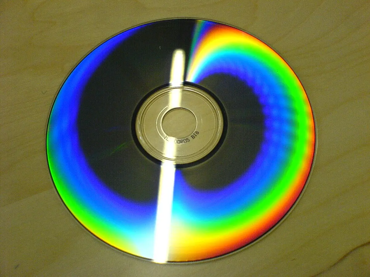
A plane transmission grating is a flat sheet of glass or plastic with parallel lines ruled or etched on it, which light passes through. A reflection grating has its lines on a mirror, and works the same way with the light bouncing off it. The tracks of a CD or DVD are a reflection grating: their spiral is about 1.6 µm from one turn to the next on a CD, 0.74 µm on a DVD, so sunlight or a tube light reflected from them breaks into bright bands of color.
Grating and prism
A prism also spreads white light into a spectrum, but by refraction: each color has its own refractive index in glass Grade 11: Grade 11, Dispersion. A grating does it by diffraction and interference.
| Prism | Grating | |
|---|---|---|
| How it spreads colors | refraction (the refractive index depends on λ) | diffraction and interference () |
| Bent most | violet | red |
| Number of spectra | one | several orders on both sides, plus white straight through |
| Measuring λ | needs the glass’s refractive index for each color | from and alone: |
Because a grating turns light through large angles, tens of degrees, its angles can be measured precisely, and the wavelength follows straight from . That is why gratings measure wavelength more accurately than a prism, or than interference experiments such as Young’s, whose fringes are only a fraction of a degree apart. Gratings are at the heart of the spectrometers that find what stars are made of, test medicines and water, and sort colors of light in fiber-optic cables.
White light falls on a diffraction grating. In the first-order spectrum, which color is turned through the largest angle?
Pick an answer to see why.
12.5 Resolving power of optical instruments
Look at two car headlights coming towards you on a long straight road at night. Far away they merge into one light; as the car comes closer, there is a moment when you can just see that there are two. Your eye has resolved them.
The resolving power of an optical instrument is its ability to show two closely spaced objects, or fine details, as separate. It depends on the wavelength of the light used, on the diameter of the aperture (in a telescope or the eye), and on the numerical aperture (in a microscope).
Why no image is a point
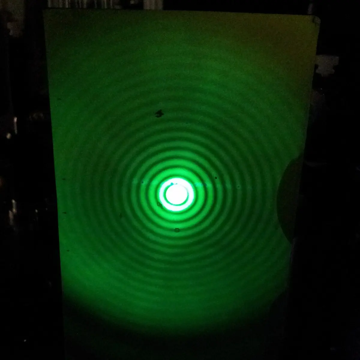
Every lens, mirror or pupil is a circular aperture, and light passing through it is diffracted, just as through a slit. So even a perfect lens can’t make a point image of a point object, such as a star. It makes a small bright disc surrounded by faint rings, the Airy pattern (after the astronomer George Airy, who worked it out in 1835). Its bright center is called the Airy disc. The angle from the center of the disc to its first dark ring is
for a circular aperture of diameter . It is like the slit’s , with an extra factor 1.22 because the aperture is round. The smaller the aperture, the bigger the disc: this is the effect noticed “when the size of the aperture is comparable to the wavelength”, but it is there for every aperture, only smaller for big ones.
Rayleigh’s criterion
Two point sources close together each make their own Airy pattern. If the two patterns overlap too much, they blur into one blob and can’t be told apart. In 1879 Lord Rayleigh suggested a simple rule for when they just can be:
Rayleigh’s criterion: two point sources are just resolved when the central maximum of one image falls on the first minimum of the other.
At that separation, the combined brightness dips by about 26 % between the two peaks, just enough for the eye to see two (Figure 12.11). Farther apart, they are clearly resolved; closer, the dip disappears and they are not resolved.
The limit of resolution is the smallest separation (or angle) at which two objects can still be resolved: the smaller it is, the finer the detail the instrument shows. The resolving power is its reciprocal.
12.5.1 Resolving power of a microscope
In a microscope, the object is very close to the objective lens, and what matters is the smallest distance between two points of the object that can be seen separately. The objective takes in a cone of light from each point of the object. If the semi-vertical angle of that cone is (Figure 12.12), and the space between the object and the lens is filled with a medium of refractive index , the smallest resolvable distance is
The quantity is called the numerical aperture (NA) of the objective; it is engraved on every objective lens (0.25, 0.65, 1.25…). The resolving power of a microscope is the reciprocal of the smallest separation:
So a microscope resolves finer detail:
- with a larger numerical aperture: an objective that is wide and very close to the object takes in a wider cone (larger ); and putting a drop of cedarwood or immersion oil () between the object and an oil-immersion objective raises from 1 (air) to about 1.5;
- with shorter wavelengths: blue or ultraviolet light resolves finer detail than red. An electron microscope goes much further: electrons behave as waves too, whose wavelength can be a hundred thousand times shorter than light’s.
12.5.2 Resolving power of a telescope
A telescope looks at objects very far away, such as two stars of a double star, so what matters is the smallest angle between them. By Rayleigh’s criterion, the smallest angle that a telescope (or any circular aperture) of diameter can resolve is the radius of the Airy disc:
where is the angular separation (in radians) of two objects that are just resolved, is the wavelength of the light and the diameter of the telescope’s objective lens or mirror. The resolving power is the reciprocal of this limit:
A smaller means better resolution. So a telescope resolves finer detail with a larger objective. That is the main reason astronomers build ever bigger telescopes (the other is that a larger aperture collects more light, so fainter objects can be seen). Increasing the focal length or the magnification of the eyepiece makes the image bigger, but not sharper: it only enlarges the blur.
Which change lets a telescope resolve two stars that are closer together in the sky?
Pick an answer to see why.
Points to note
- Why diffraction of light is seldom noticed. Light’s wavelength is about m (a micrometer, or less), and gaps and obstacles that small are rare in daily life, so light’s diffraction is too small to notice. Sound’s wavelength is around 1 m, the size of doors, windows and people, so sound diffracts all the time. That is why you can hear a person behind a wall but can’t see them: sound bends round the wall a lot, light only a tiny amount, far too little to reach your eye.
- Holding your hand at arm’s length blocks the sunlight from your eyes, but not the sound of the traffic from your ears, for the same reason.
- A chest X-ray shows no diffraction pattern, though the ribs are evenly spaced like a grating. X-rays have a wavelength of about m, while the ribs are centimeters apart: about a hundred million times too far apart to act as a grating for them. (The rows of atoms in a crystal, about m apart, do diffract X-rays: that is how the structures of salt, DNA and many medicines were found.)
- If a single-slit apparatus is put under water, with nothing else changed, the wavelength of light falls to , about three quarters (75 %) of its value in air (a decrease of 25 %), and the width of the central maximum, , shrinks in the same ratio.
Exercise
Choose the correct option
- What is the angular position of the first diffraction minimum in a single-slit diffraction pattern, if the wavelength of light is and the slit width is ?
Pick an answer to see why.
- What happens to the diffraction pattern when the wavelength of light is increased in a single-slit diffraction experiment?
Pick an answer to see why.
- If the slit width in a single-slit diffraction experiment is halved, what will happen to the angular width of the central maximum?
Pick an answer to see why.
- What happens if red light is used in place of blue light in diffraction?
Pick an answer to see why.
- What makes the distance between consecutive maxima in a single-slit diffraction pattern increase?
Pick an answer to see why.
- What is the resolving power of an optical instrument?
Pick an answer to see why.
- Which is the best reason why light seems to travel in straight lines?
Pick an answer to see why.
- Which is the correct expression for the resolving power of a microscope?
Pick an answer to see why.
- Which of the following increases the resolving power of a microscope?
Pick an answer to see why.
- Which change in the design of a telescope increases its resolving power?
Pick an answer to see why.
- What determines the diffraction limit of resolution in an optical instrument?
Pick an answer to see why.
- What happens to the resolving power of a microscope if the objective lens has a larger numerical aperture?
Pick an answer to see why.
Answer these questions
Diffraction is a key wave phenomenon: light bends round obstacles or through small openings, making characteristic patterns on a screen.
- a.Define diffraction of light. Under what conditions is diffraction significant?
- b.Differentiate interference from diffraction, based on their sources and on how the fringes form.
- c.Light of wavelength 500 nm passes through a single slit of width 0.1 mm. Calculate the angular width of the central maximum, and its width on a screen 2 m away.
Hint
Answer
When light meets obstacles or narrow openings, it bends and spreads: diffraction. Under what conditions does this bending become prominent, and how do the positions of the source and the screen decide which type of diffraction pattern is seen?
Answer
The bending of light becomes more prominent in narrow apertures, and is classified into distinct types.
- a.Compare Fresnel and Fraunhofer diffraction, with diagrams or descriptions of the setup.
- b.Derive the condition for minima in single-slit diffraction using geometry.
- c.A single slit of width 0.2 mm is lit by light of wavelength 600 nm. Calculate the angular position of the first minimum.
- d.Why is light partially polarized when it reflects from a non-metallic surface?
Hint
Answer
Diffraction gratings disperse light into its components, helping us analyze wavelengths.
- a.What is a diffraction grating? Mention two practical applications.
- b.State and explain the grating equation for constructive interference.
- c.A diffraction grating has 6000 lines/cm. Find the angle of the second-order maximum for light of wavelength 500 nm.
Answer
Diffraction limits the resolving power of optical instruments like microscopes and telescopes.
- a.Define resolving power and explain its relation to diffraction.
- b.State Rayleigh’s criterion and its relevance to angular resolution.
- c.Calculate the smallest angular separation between two objects that a telescope with an aperture of 0.2 m can resolve, using light of wavelength 550 nm.
Answer
The effect of diffraction depends on the relative sizes of the aperture and the wavelength.
- a.Why is diffraction insignificant for everyday objects?
- b.How does diffraction affect the performance of optical instruments?
- c.A slit of width 0.05 mm is lit by monochromatic light of wavelength 650 nm. Calculate the angular position of the second diffraction minimum.
Answer
The behavior of light passing through narrow openings gives insight into the visibility of fringes and diffraction patterns.
- a.What is the effect on the diffraction pattern if the slit width decreases?
- b.Compare the intensity and width of the central maximum in single-slit diffraction with those of the central bright fringe in double-slit interference.
- c.A laser beam of wavelength 650 nm passes through a slit of width 0.1 mm. Calculate the width of the central maximum on a screen 1.5 m away.
Answer
The single-slit diffraction pattern is determined by the angular spread and the size of the aperture.
- a.Define angular width in single-slit diffraction.
- b.Explain how diffraction influences the resolution of optical instruments.
- c.Monochromatic light of wavelength 550 nm falls normally on a grating having 4000 lines/cm. Find the angle of the first-order maximum.
- d.How does Huygens’ principle explain the diffraction of light?
Answer
The grating element is key to understanding diffraction orders.
- a.What is the grating element? How is it related to the number of lines per cm?
- b.Derive the expression for the angular positions of the maxima in grating diffraction.
- c.Calculate the number of diffraction orders observable with light of wavelength 500 nm and a grating with 5000 lines/cm.
- d.Explain the relationship between the angular width of the central maximum and the wavelength of light in single-slit diffraction.
Hint
Answer
- a.Explain the pattern observed on the screen in single-slit diffraction, with a diagram.
- b.Derive the condition for the first minimum in Fraunhofer diffraction.
- c.Monochromatic light of wavelength 650 nm falls on a single slit of width 0.15 mm. The diffraction pattern is observed on a screen 2 m from the slit. Calculate the angle at which the second diffraction minimum occurs.
Answer
A single-slit diffraction pattern is formed on a screen at a distance from a slit of width , as in Figure 12.4.
- a.Write the angular condition for minima in single-slit diffraction.
- b.Derive the expression for the linear position of the first minimum.
- c.If mm, m and nm, calculate the distance of the first minimum from the central maximum.
Answer
Diffraction gratings disperse light into its spectral components, using the interference of waves diffracted by many closely spaced slits.
- a.How does a diffraction grating disperse light into its components?
- b.Derive the grating equation used to calculate diffraction angles.
- c.A diffraction grating has 5000 lines per cm. Calculate the angle of the second-order maximum for light of wavelength 500 nm.
Answer
Diffraction is broadly classified into two types, Fresnel and Fraunhofer, each occurring under specific conditions and producing distinct patterns.
- a.State the conditions for Fresnel and Fraunhofer diffraction.
- b.Discuss the differences in the fringe patterns formed.
- c.In a Fraunhofer diffraction experiment with a single slit, light of wavelength 450 nm produces a central maximum 2 cm wide on a screen 1.5 m from the slit. Calculate the slit width.
Answer
The width of a slit plays a crucial role in shaping the diffraction pattern, influencing how light spreads and forms maxima and minima on a screen.
- a.How does changing the slit width affect the diffraction pattern?
- b.Derive the relation between the slit width, the wavelength and the width of the central maximum.
- c.Light of wavelength 700 nm passes through a slit of width 0.2 mm. Determine the angular width of the central maximum.
Answer
Fraunhofer diffraction through a single slit shows the wave nature of light, making a pattern of bright and dark fringes when light passes through a narrow aperture and is observed at a distance or with a lens.
- a.Describe the conditions needed to observe Fraunhofer diffraction through a single slit.
- b.Why is the central maximum wider and brighter than the others?
- c.Derive the condition for the angular positions of the minima.
- d.Monochromatic light of wavelength 600 nm falls on a single slit of width 0.15 mm. Calculate the angular position of the first diffraction minimum.
Answer
In diffraction grating experiments, light is diffracted through thousands of closely spaced slits, producing sharp maxima at certain angles. These patterns are used to calculate wavelengths, analyze spectra and resolve fine details.
- a.Define “grating element” and its relation to line density.
- b.Why does increasing the number of lines improve a grating’s resolution?
- c.Light of wavelength 520 nm falls normally on a grating with 6000 lines/cm.
- i.Find the grating element.
- ii.Calculate the maximum order of diffraction that can be observed with this light.
- iii.Find the angle of diffraction of the second-order maximum.
Answer
Printable PDFs
- The unit as a book (A5) 17 pages Answers as an A4 booklet, 5 sheets
- Study notes 3 pages
- Worksheet 4 pages Answer key
- Harder practice questions 2 pages Answer key
Quiz yourself: Energy, Heat, Light and Sound, Grades 5–12 →
Practice every question in the book, and keep track of the ones you miss →
A companion to your textbook, not a replacement for it: study from the book your school uses, and where the two differ, follow your teacher. Found a mistake? Please tell us.