
A cup of hot tea left on the table always cools to the temperature of the room; it never takes heat from the room and starts to boil. A drop of ink spreads through a glass of water, and never gathers itself back into a drop. A motorbike’s engine burns petrol, and most of the fuel’s energy leaves as heat from the exhaust and the hot engine, however well it is made. None of this breaks the first law: energy would be conserved just as well the other way round. Something else decides which way things go.
That something is the second law of thermodynamics. It explains why heat flows from hot to cold by itself, why no engine can turn all its heat into work, how a refrigerator manages to pump heat “uphill”, and why the best possible engine’s efficiency depends only on two temperatures. It ends with entropy, the quantity that measures how spread out energy is, and that never decreases in the universe as a whole.
5.1 Introduction
The first law of thermodynamics (Unit 4) says that heat and work can be changed into each other, with energy always conserved. But it is silent on four things: which way a change goes by itself, how much of the heat can become work (the efficiency), whether a process is reversible, and under what conditions heat can be turned into work. The second law of thermodynamics was brought in to answer them.
The second law is about the direction of natural processes. It explains:
- why heat flows by itself from a hotter body to a colder one, and never the other way;
- why every natural process is irreversible: in each, the total entropy (Section 5.8) of the system and its surroundings increases;
- why no engine can be 100% efficient: some of the heat it takes in must always be passed on to something colder, where it can no longer do work;
- how heat engines and refrigerators work, and the best that each can possibly do.
It became a cornerstone of physics and of engineering, and of chemistry and biology too: it tells which reactions can go by themselves.
5.2 Second law of thermodynamics
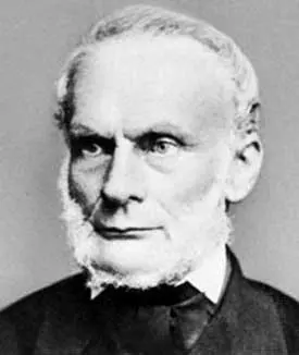
The second law of thermodynamics is the basic principle that gives the direction of natural processes and the limits of turning heat into work. It can be stated in many ways; two are famous, the Kelvin–Planck statement and the Clausius statement. They look at different things, an engine and a refrigerator, but they are equivalent: if either one were false, the other would be false too.
Kelvin–Planck statement (about a heat engine)
It is impossible to make an engine, working in a cycle, that takes heat from a single reservoir and converts all of it into work.
So every heat engine takes in heat from a hot source, turns part of it into work, and must give out the rest, as waste heat, to a colder sink. An engine needs both a source at a higher temperature and a sink at a lower one, and no heat engine can be 100% efficient. (The words “in a cycle” matter: a gas expanding at constant temperature does turn all the heat it takes in into work, as in Unit 4, but then it is left at a larger volume, and can’t keep doing it.)
Clausius statement (about a refrigerator)
Heat cannot flow by itself from a colder body to a hotter body; for that to happen, external work must be done.
Heat flows naturally from a hotter body to a colder one; to make it go the other way needs work. That is what a refrigerator does: an electric motor does work on its working substance (the refrigerant), which takes heat from the cold inside of the refrigerator and gives out a larger amount of heat to the warmer room.
Why the two statements are equivalent
Suppose someone did build a perfect engine that broke the Kelvin–Planck statement: it takes heat from a hot body and turns all of it into work , giving no heat to anything colder. Use that work to drive an ordinary refrigerator working between the same two bodies (Figure 5.2). The refrigerator takes heat from the cold body and gives to the hot body.
Treat the two machines as one. The hot body has lost and gained : a net gain of . The cold body has lost . No work came in from outside. So heat has flowed from the cold body to the hot one by itself, which breaks the Clausius statement. In the same way, a refrigerator that broke the Clausius statement could be joined to an ordinary engine to make an engine that breaks the Kelvin–Planck statement. Either both statements are true, or neither is; they are two faces of one law.
An inventor claims an engine that runs in a cycle, takes 1000 J of heat from a hot boiler and does 1000 J of work, and needs no cooling. It breaks:
Pick an answer to see why.
Comparing the first and second laws
Both laws are about energy, but they say different things: the first, how much energy there is; the second, which way it goes and how much of it can be used.
| First law of thermodynamics | Second law of thermodynamics | |
|---|---|---|
| Direction of heat flow | Says nothing about it: by the first law alone, heat could flow either way, as long as energy is conserved | Heat flows by itself only from hot to cold; to make it flow the other way needs external work |
| Efficiency of turning heat into work | Says nothing about it: by the first law alone, an engine could be 100% efficient | No heat engine working in a cycle can be 100% efficient; the best possible efficiency depends on the two temperatures (Section 5.5) |
| What it is about | The quantity of energy: conservation | The direction of processes, irreversibility, entropy |
5.3 Heat engine
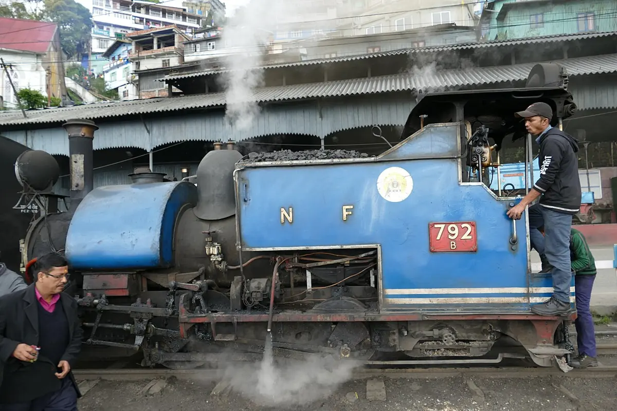
A heat engine is a device that turns heat into mechanical work by using the difference in temperature between a hot reservoir (the source) and a cold reservoir (the sink). It takes in heat from the source, does useful work, and gives out the rest of the heat to the sink. It works in a cycle, returning to its first state after each cycle, so it can keep going. There are internal combustion engines (petrol and diesel engines, jet engines) and external combustion engines (steam engines, Stirling engines, the steam turbines of coal-fired power stations). Heat engines power vehicles, generators, ships, aircraft and most of the world’s electricity.
The essential parts of a heat engine:
- Heat source (high-temperature reservoir): a body kept at a high temperature, with so large a heat capacity that any amount of heat can be taken from it without lowering its temperature. Examples: the furnace and boiler of a steam engine; the burning fuel in the cylinder of a petrol or diesel engine.
- Heat sink (low-temperature reservoir): a body kept at a low temperature, so large that any amount of heat can be given to it without raising its temperature. Examples: the atmosphere, for a petrol or diesel engine; the cooling water of a power station’s condenser, or a river.
- Working substance (working fluid): the material that takes in heat from the source, changes its temperature, pressure and volume to do work, and gives out the remaining heat to the sink. Examples: water and steam in a steam engine; air and fuel gases in a petrol or diesel engine.
Thermal efficiency of a heat engine
Let the working substance of an engine take in heat from a source at temperature (in kelvin), do work , and give out the remaining heat to a sink at the lower temperature (Figure 5.3). Over a whole cycle the working substance returns to its first state, so its internal energy doesn’t change, and by the first law the heat turned into work is
The thermal efficiency (eta) of the engine is the ratio of the work it does to the heat it takes from the source:
As a percentage, .
For the efficiency to be 100%, would have to be zero: no heat given to the sink. That is exactly what the Kelvin–Planck statement rules out. So is always greater than zero, and the efficiency of a heat engine is always less than 100%.
An engine takes in 500 J of heat from its source in each cycle and gives out 350 J to its sink. Its efficiency is:
Pick an answer to see why.
5.4 Carnot’s theorem
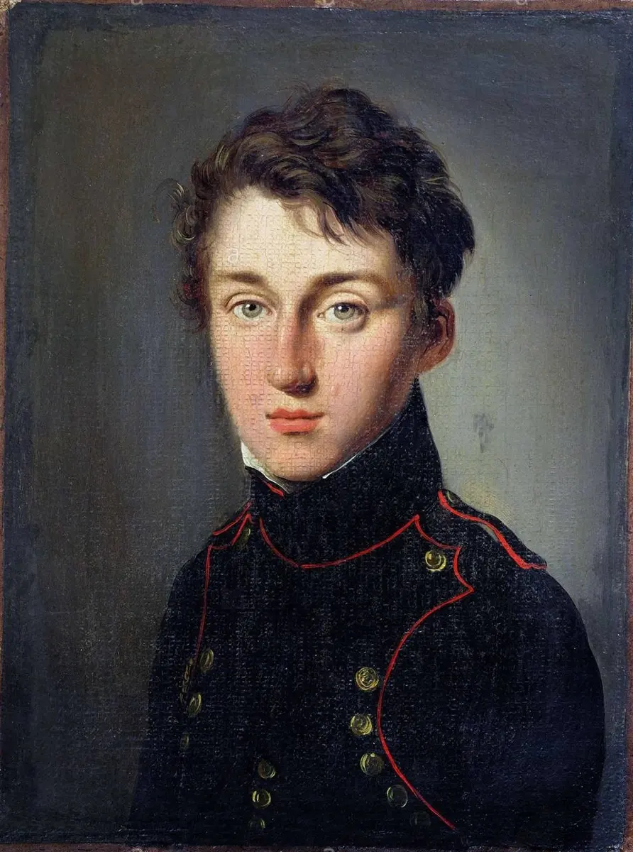
In 1824 the young French engineer Sadi Carnot worked out the best that any heat engine can possibly do. His theorem sets a fundamental limit on the efficiency of heat engines: the efficiency of a reversible engine depends only on the temperatures of its source and sink, not on its working substance.
Carnot’s theorem:
All reversible engines working between the same two reservoirs have the same efficiency, and no engine working between the same two reservoirs can have a greater efficiency than a reversible engine.
So no heat engine can be more efficient than Carnot’s engine working between the same two temperatures.
Why? Suppose some engine X were more efficient than a reversible engine R between the same two reservoirs. Since R is reversible, it can be run backwards as a refrigerator. Let X drive R backwards. X takes heat from the hot reservoir and does work; being more efficient than R, it can supply all the work R needs while taking less heat from the hot reservoir than R puts back into it. Taken together, the two machines do no net work, yet the hot reservoir gains heat and the cold reservoir loses the same amount: heat has flowed from cold to hot by itself, against the Clausius statement. So X can’t exist. The same argument, with any two reversible engines, shows that neither can beat the other, so all reversible engines between the same reservoirs are equally efficient.
Two reversible engines work between the same boiler and the same river. One uses steam, the other air. Which is more efficient?
Pick an answer to see why.
5.5 Carnot’s engine and Carnot’s cycle
Carnot’s engine is an imaginary, ideal engine designed to get the greatest possible efficiency from a given source and sink. It is free of all the imperfections of real engines: no friction, no heat leaking, and every step reversible. Its working cycle, Carnot’s cycle, is made of two isothermal and two adiabatic processes (Unit 4). Its parts (Figure 5.6):
- Source: a hot body of infinite heat capacity, kept at a constant high temperature . Any amount of heat can be taken from it without lowering its temperature. For example, a furnace or a boiler.
- Sink: a cold body of infinite heat capacity, kept at a constant low temperature . Any amount of heat can be given to it without raising its temperature. For example, the atmosphere, or the water of a river or heat exchanger.
- Insulating stand: a perfectly non-conducting platform. On it, the cylinder can exchange no heat.
- Working substance: an ideal gas.
- Cylinder and piston: the gas is held in a cylinder with perfectly non-conducting walls but a perfectly conducting base, closed by a frictionless, weightless, airtight and non-conducting piston.
Working of Carnot’s engine
Take moles of ideal gas in the cylinder, starting at point on the P–V diagram (Figure 5.7). The cycle has four steps.
Step 1: isothermal expansion (AB). The cylinder is placed on the source at , and the gas expands slowly at that temperature from to . It takes in heat from the source through the base. For an isothermal process , so all of comes out as work (Unit 4, Section 4.11):
Step 2: adiabatic expansion (BC). The cylinder is moved onto the insulating stand, and the gas keeps expanding, now with no heat coming in, from to . It does work out of its own internal energy, so it cools until it reaches the sink’s temperature . By Section 4.12,
Step 3: isothermal compression (CD). The cylinder is placed on the sink at , and the gas is compressed slowly from to . Work is done on the gas, and since its temperature doesn’t change, it gives out an equal amount of heat to the sink:
( is negative, work done on the gas; is the heat given out, a positive amount.)
Step 4: adiabatic compression (DA). The cylinder is moved back onto the insulating stand, and the gas is compressed from back to . The work done on it raises its internal energy, and its temperature rises back to :
The gas is back where it started, and the engine is ready for the next cycle.
Net work and efficiency
- The net work done in one cycle is the sum of the four:
The two adiabatic works cancel, so
- B and C lie on the same adiabat, and so do D and A. By constant (Section 4.12):
- Dividing (5.6) by (5.7):
- Putting (5.8) into (5.5):
Since and , is positive: the engine does net work in each cycle, the area enclosed by the loop, and repeating the cycle gives as much work as we want.
- The efficiency is
Comparing with , for a Carnot engine
The efficiency of Carnot’s engine depends only on the temperatures of the source and the sink, in kelvin. It doesn’t depend on the working substance, or on the design of the engine. That is why all reversible engines working between the same two temperatures have the same efficiency, whatever they are made of. It also shows two things about every engine:
- To raise the efficiency, make the source hotter or the sink colder. A power station’s turbines run on steam as hot as their metal can stand, and its condensers are cooled by a river.
- The efficiency could only be 100% if K, and absolute zero can’t be reached: so no engine is ever 100% efficient.
A Carnot engine works between a source at 600 K and a sink at 300 K. To raise its efficiency the most, which is better: raising the source by 100 K, or lowering the sink by 100 K?
Pick an answer to see why.
5.6 Refrigerator
A refrigerator is a heat engine run in reverse. It takes heat from a region at a low temperature (the inside of the refrigerator) and gives it out to a region at a higher temperature (the room), using work, usually electrical energy, to move the heat against its natural direction of flow (Figure 5.8). An ideal refrigerator works on a reversed Carnot cycle.
Its cycle has four parts (Figure 5.9). The refrigerant, a liquid that boils at a low temperature, circulates in a closed loop of pipes:
- Evaporation: in the evaporator coils inside the cabinet, the cold, low-pressure liquid boils, taking its latent heat, , from the food and air inside. The inside cools.
- Compression: the compressor, driven by an electric motor, squeezes the vapor. Work is done on it, and like any gas compressed fast (Section 4.12), it gets hot, hotter than the room.
- Condensation: in the condenser coils at the back, the hot vapor gives out heat to the room and condenses back to a liquid.
- Expansion: the liquid passes through a narrow expansion valve (or a thin capillary tube). Its pressure drops, part of it boils off at once, and it cools below the temperature inside the cabinet, ready to take in heat again.
A thermostat switches the compressor on and off to keep the inside at the chosen temperature.
Let the refrigerant take heat from the inside at temperature , with work done by the compressor, and give out heat to the room at the higher temperature . By the first law, : the room receives more heat than was taken from inside. Here the work is what we pay for, and the heat removed from inside is what we want.
The performance of a refrigerator is measured by its coefficient of performance (COP): the ratio of the heat taken from the cold body to the work done by the compressor:
Dividing the top and bottom by :
For an ideal (Carnot) refrigerator, , so
So the coefficient of performance of an ideal refrigerator depends only on the two temperatures: every reversible refrigerator working between the same two temperatures has the same β, whatever its refrigerant. The smaller the difference , the larger β: less work is needed to move each joule of heat. A real refrigerator always has a smaller β than . Unlike an efficiency, β is usually greater than 1: a refrigerator can move several joules of heat for each joule of work.
A refrigerator takes 300 J of heat out of its cold inside while its compressor does 100 J of work. How much heat does it give out to the kitchen?
Pick an answer to see why.
5.7 Internal combustion engines
Heat engines are of two kinds, which differ in where the fuel burns. In an external combustion engine, such as a steam engine, the fuel burns outside, under a boiler, and the heat passes through the boiler’s walls into the working substance. In an internal combustion engine, the fuel burns inside the cylinder itself, and the hot gases it makes push directly on the moving part, a piston or a turbine. Examples: the engines of cars, buses, lorries, tractors and motorbikes; the jet engines of aircraft.
Internal combustion engines are smaller and lighter than external combustion engines of the same power, and can be more efficient, but they burn fuel inside a machine that moves, and add to air pollution and noise. The two main kinds are the petrol engine and the diesel engine.
Petrol engine (Otto engine)
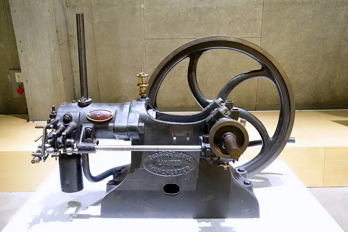
A petrol engine (gasoline engine) is a four-stroke internal combustion engine whose fuel is lit by a spark. Its ideal cycle is the Otto cycle, after the German engineer Nikolaus August Otto, who built the first successful four-stroke engine in 1876. Its working substance is air mixed with a little petrol vapor (about 2% by volume).
It has a metal cylinder with an intake valve I, a spark plug S and an outlet (exhaust) valve O. A piston moves in the cylinder, joined by a connecting rod to a crank, which turns the piston’s up-and-down motion into the turning of a shaft, and a heavy flywheel keeps the shaft turning smoothly through the strokes that do no work. Cams on a shaft turned by the engine open and close the valves at the right moments. The four strokes (Figure 5.10) take two turns of the crank:
- Suction (intake) stroke: the intake valve opens, the outlet valve stays closed, and the piston moves out (down). The pressure inside falls slightly, and the air–petrol mixture is drawn in (from the carburetor, or from fuel injectors in a modern engine). When the piston reaches the end, the intake valve closes, with the mixture at volume and atmospheric pressure: line AB on the P–V diagram (Figure 5.11).
- Compression stroke: both valves are closed, and the piston moves in, compressing the mixture adiabatically to the small volume : line BC. Its pressure and temperature rise. At the end, the spark plug fires, and the mixture burns almost at once, before the piston has time to move: heat is added at constant volume , and the temperature and pressure jump: line CD.
- Working (power) stroke: the hot, high-pressure gas expands adiabatically, driving the piston out hard and doing work, until its volume is again : line DE. This is the only stroke in which the engine does work; the flywheel carries the engine through the other three.
- Exhaust stroke: the outlet valve opens near the end of the working stroke, and the pressure drops at once to atmospheric as hot gas rushes out, the volume staying almost : heat leaves with it, line EB. Then the piston moves in and pushes the rest of the burnt gas out at atmospheric pressure, down to the small volume left above the piston (the clearance volume, where the next charge will be squeezed), line BA. The cycle starts again.
Lines AB and BA cancel (the same line, gone both ways), so the work done in a cycle is the area of the loop BCDEB.
Efficiency of the petrol engine
The compression ratio is the ratio of the largest volume to the smallest: . Treat the working substance as moles of air, an ideal gas with heat capacity and ratio γ, and call the temperatures at B, C, D, E .
- Heat in, at constant volume (CD): . Heat out, at constant volume (EB): .
- So
- 3.BC is adiabatic, from to : , so . DE is adiabatic, from to : likewise .
- 4.So , and
The efficiency of the ideal petrol engine depends only on its compression ratio (and γ): the more the mixture is squeezed, the more efficient the engine. For air, γ ≈ 1.4; with compression ratios of 8 to 12, the ideal efficiency is 56% to 63%. (Real petrol engines, with friction, heat lost through the cylinder walls and burning that takes time, reach 25% to 35%.)
Why not squeeze harder? A petrol–air mixture squeezed too much gets so hot that parts of it catch fire by themselves before the flame from the spark reaches them. The pressure spikes, making a metallic rattle called knocking, which wastes power and can damage the engine. That keeps the compression ratio of petrol engines to about 12 or less (higher-octane petrol resists knocking better).
Uses of petrol engines: cars, motorbikes and scooters, light vans and trucks; small aircraft; pumps and compressors; small boats; generators, lawn mowers, chainsaws and other power tools.
Merits: light and compact, with a high power-to-weight ratio; smooth and quiet running; cheaper to buy; easy to start; can run at high speeds (high revolutions per minute); little visible smoke; petrol is easy to get; maintenance is cheap.
Demerits: less fuel-efficient than a diesel engine; petrol costs more; shorter working life and less durable; not suited to heavy loads; risk of knocking (pre-ignition); petrol vapor catches fire easily; limited industrial use; spark plugs can fail.
Diesel engine
A diesel engine is a four-stroke internal combustion engine that needs no spark: the fuel catches fire in the hot compressed air. It is more efficient than a petrol engine. It is named after the German engineer Rudolf Diesel, who designed it in the 1890s. Its working substance is air, with diesel oil as the fuel.
Its cylinder has an intake valve, a fuel injector (in place of the spark plug) and an exhaust valve. Its build and working are much like a petrol engine’s:
- Suction stroke: the intake valve opens, the injector and exhaust valve are closed, and the piston moves out, drawing in air only, to volume at atmospheric pressure: line AB (Figure 5.13).
- Compression stroke: all valves closed, the piston compresses the air adiabatically: line BC. Its compression ratio is much higher than a petrol engine’s, 14 to 25, so the air becomes very hot, 500 °C or more. At the end, the injector sprays diesel into it, and the fuel catches fire by itself in the hot air. The fuel keeps burning as it is sprayed in while the piston starts to move out, so heat is added at roughly constant pressure, line CD, until the injection stops at D.
- Working stroke: the hot gas expands adiabatically, driving the piston out and doing work: line DE.
- Exhaust stroke: the exhaust valve opens and the pressure falls to atmospheric, heat leaving with the gas at almost constant volume, line EB; then the piston pushes the burnt gas out at atmospheric pressure, back to the clearance volume, line BA.
Efficiency of the diesel engine
The difference from the Otto cycle is that the heat comes in at constant pressure, so it carries a second ratio, the cut-off ratio , how much the gas expands while fuel is burning.
- Heat in, at constant pressure (CD): . Heat out, at constant volume (EB): . So, with ,
- 2.BC adiabatic: . CD at constant pressure: . DE adiabatic from to : .
- 3.Putting these in:
The second factor is always greater than 1, so at the same compression ratio a diesel cycle is a little less efficient than an Otto cycle. But the diesel engine compresses only air, which can’t knock, so it can use much higher compression ratios, and that makes it the more efficient engine. With : about 59% at and 68% at in theory; real diesel engines reach 35–45%, and the largest ship engines over 50%.
Uses of diesel engines: cars, buses and lorries; tractors and irrigation pumps; excavators, bulldozers, cranes and generators; ships, boats and fishing vessels; power plants and backup generators; military vehicles and submarines; railway locomotives.
Merits: high fuel efficiency; durable, with a long working life; diesel is cheaper (in many countries) and less of a fire risk; better for heavy loads, with strong pulling force at low speed; useful for a wide range of jobs.
Demerits: costs more to buy; heavier and larger for the same power; noisier, with more vibration; servicing and repairs cost more; more soot and nitrogen oxides in the exhaust unless cleaned; not well suited to light vehicles.
| Petrol engine (Otto cycle) | Diesel engine (Diesel cycle) | |
|---|---|---|
| Takes in | air–petrol mixture | air only |
| Ignition | by a spark plug | by the heat of compression (no spark) |
| Fuel enters | with the air, in the suction stroke | sprayed in by an injector at the end of compression |
| Heat added | at constant volume | at (roughly) constant pressure |
| Compression ratio | about 8 to 12 (limited by knocking) | about 14 to 25 |
| Ideal efficiency | : 56–63% | about 59–68% (cut-off ratio 2) |
| Real efficiency | about 25–35% | about 35–45% |
| Build | lighter, cheaper | heavier, stronger, dearer |
The worked examples on Carnot’s engine (Examples 5.1–5.3) are in Section 5.5, beside the formula they use.
Why don’t petrol engines use compression ratios of 20, like diesel engines, to be more efficient?
Pick an answer to see why.
5.8 Entropy
Entropy is the key to the direction of natural processes and to the limits of efficiency. It is a state variable, like temperature or internal energy (Unit 4): a system in a given state has a definite entropy. It was first brought in by Clausius, from the study of heat engines, and it was later understood as a measure of the disorder (randomness) of the particles in a system, or more exactly, of how spread out its energy is among them. The more spread out the energy, the less of it is available to do useful work.
Entropy can’t be felt or seen, as temperature or pressure can; we know it through the changes it measures. A small change in entropy is defined as the heat given to a system reversibly, divided by the absolute temperature at which it is given:
where is the change in entropy, the heat added and the absolute temperature at which it is added. The unit of entropy is J/K. Heat added raises a system’s entropy; heat taken out lowers it. The same heat raises the entropy more at a low temperature than at a high one, as a coin matters more to a poor person than a rich one.
- The molecules of a solid are the most ordered, held in place; those of a gas the least, flying anywhere. So, for the same substance, entropy of gas > entropy of liquid > entropy of solid.
- In a reversible adiabatic process no heat is exchanged, so : the entropy stays constant. (An irreversible adiabatic process, like the free rushing of a gas into a vacuum, raises the entropy, though no heat flows.)
- To lower the entropy of a system, heat must be taken out of it. A cup of tea cooling on the table loses entropy by itself, because the cooler room gains more. But to cool something below the temperature of its surroundings, as when food is cooled in a refrigerator on a warm day, work must be done.
600 J of heat is given reversibly to a large body at 300 K, and another 600 J to a large body at 600 K. Whose entropy rises more?
Pick an answer to see why.
Second law in terms of entropy
In every process, the total entropy of a system and its surroundings taken together (or of any isolated system) either increases or, for a reversible process, stays the same. It never decreases.
The entropy of one part can fall, but only if another part’s rises by more. When water freezes in a freezer, its entropy falls, but the refrigerator gives the room more than enough heat to make up for it.
In a Carnot cycle, the gas gains entropy from the source and gives out to the sink. Since , these are equal: the total entropy doesn’t change, as it shouldn’t for a reversible cycle. An engine that gave out less heat than , to beat Carnot’s efficiency, would destroy entropy: the second law forbids it.
The principle of increase of entropy (or of the degradation of energy): almost every natural process is irreversible, so the entropy of the universe keeps increasing. Energy is never destroyed, but each irreversible process leaves it more spread out, less able to do work. Looking far ahead, physicists have imagined a heat death of the universe, in which everything has come to one temperature and no work can be done any more.
A glass of water is put in a freezer and turns to ice. What happens to entropy?
Pick an answer to see why.
Exercise
Choose the correct option
- The second law of thermodynamics states that:
Pick an answer to see why.
- Which of the following statements about entropy is correct?
Pick an answer to see why.
- The efficiency of a Carnot engine depends on:
The textbook’s option b, “the temperature difference between heat reservoirs”, isn’t enough on its own: 500 K and 300 K give 40%, but 1000 K and 800 K only 20%, with the same 200 K difference. It is replaced below.
Pick an answer to see why.
- The coefficient of performance (COP) of a refrigerator is defined as:
Pick an answer to see why.
- In an ideal Otto cycle, the efficiency depends on:
Pick an answer to see why.
- A Carnot engine works between 500 K and 300 K. What is its efficiency?
Pick an answer to see why.
- A refrigerator absorbs 200 J of heat from a cold reservoir, with 50 J of work done. What is its COP?
Pick an answer to see why.
- A diesel engine has a compression ratio of 18 and a cut-off ratio of 2. If γ = 1.4, its ideal efficiency is closest to:
The textbook gives only the compression ratio and expects the petrol engine’s formula, , which is not the diesel cycle’s. A diesel cycle’s efficiency also needs its cut-off ratio, so the question and its options are corrected below.
Pick an answer to see why.
- A Carnot refrigerator works between 250 K and 300 K. If it extracts 500 J of heat from the cold reservoir, what work input does it need?
Pick an answer to see why.
- A heat engine absorbs 600 J of heat from a reservoir at 500 K and rejects heat to a reservoir at 300 K. What is the greatest possible work it can do?
Pick an answer to see why.
- A Carnot engine works between 1000 K and 400 K and produces 2000 J of work per cycle. How much heat must it absorb from the hot reservoir in each cycle?
None of the textbook’s options (3000 J, 4000 J, 5000 J, 6000 J) is right: the answer is 3333 J, so the book’s numbers don’t work. The options below are corrected, and the engine is made a Carnot engine so that the answer is fixed.
Pick an answer to see why.
Answer these questions
- a.State and explain the second law of thermodynamics, using the Kelvin–Planck and Clausius statements.
- b.Compare and contrast the first and second laws of thermodynamics in terms of the direction of heat flow and the efficiency of energy conversion.
Answer
- a.What are the essential parts of a heat engine?
- b.Draw a block diagram of a heat engine. Explain how its efficiency can be found.
- c.A heat engine absorbs 1200 J of heat from the source and rejects 700 J to the sink. Calculate i. the work done, ii. the efficiency of the engine.
- d.Why can the efficiency of a heat engine never be 100%?
Answer
- a.Describe the Carnot cycle and explain its representation on a P–V diagram.
- b.Derive the efficiency of a Carnot engine, and explain the significance of the source and sink temperatures.
- c.The efficiency of a Carnot engine is 60%. If the sink is at 300 K, what is the temperature of the source?
Answer
- a.Differentiate between the Otto and Diesel cycles. Show both on P–V diagrams.
- b.A diesel engine takes in 5000 J of heat and does 1200 J of work. Calculate the heat it rejects and its efficiency.
Answer
- a.Describe the working of a refrigerator as a reversed heat engine. Define its coefficient of performance (COP).
- b.A refrigerator removes 400 J of heat from its cold compartment and needs 100 J of work. What is its COP?
Answer
- a.What is entropy? How does it relate to disorder?
- b.Why is the entropy of the universe said to be always increasing? Give examples.
Answer
- a.Explain why no heat engine can be more efficient than a Carnot engine working between the same two temperatures.
- b.Describe the practical limitations of real engines compared with the ideal Carnot engine.
- c.A Carnot engine works between a source at 500 K and a sink at 300 K. Calculate its efficiency.
Answer
A heat engine has an efficiency of 25%. How much heat does it reject if it absorbs 600 J of heat from the source?
Answer
A Carnot engine rejects heat at 400 K and absorbs heat at 800 K. If it does 300 J of work per cycle, calculate a. its efficiency, b. the heat it absorbs per cycle.
Answer
Printable PDFs
- The unit as a book (A5) 20 pages Answers as an A4 booklet, 5 sheets
- Study notes 3 pages
- Worksheet 4 pages Answer key
- Harder practice questions 2 pages Answer key
Quiz yourself: Energy, Heat, Light and Sound, Grades 5–12 →
Practice every question in the book, and keep track of the ones you miss →
A companion to your textbook, not a replacement for it: study from the book your school uses, and where the two differ, follow your teacher. Found a mistake? Please tell us.